Our Products
Quad Occupancy Detector
See our article titled Why Detect Occupancy?
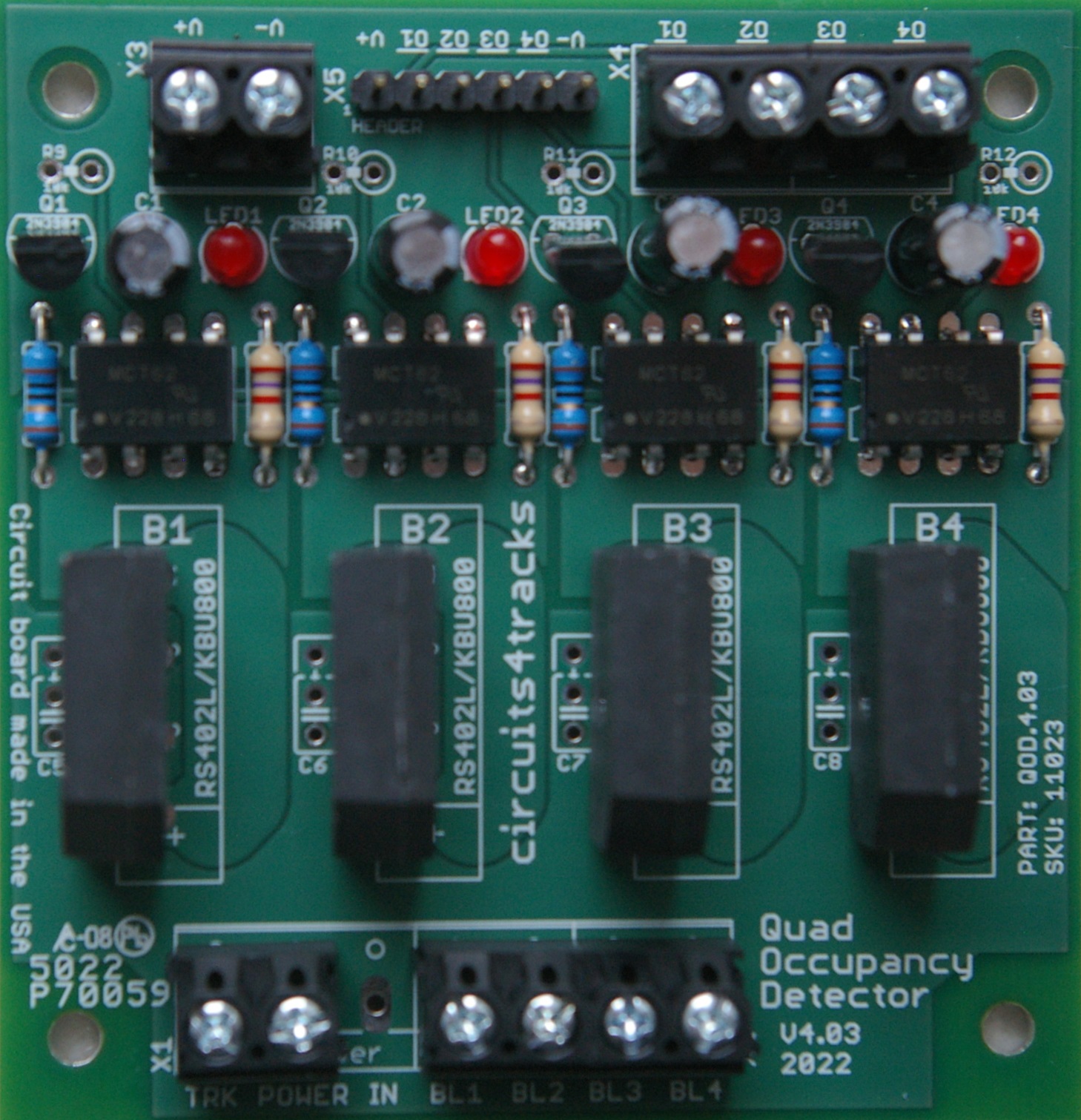 | | Specifications: | | Version: | 4.03 | | Card size: | 2.75" x 2.85" | | Mounting hole size: | 0.125"
Suitable for #4 screws | | Detectors per card: | 4
Card may be partially populated with 1, 2 or 3 detectors | | Track connector: | Screw terminal blocks
2 terminals for power input feed, 1 for each feed to block
Each terminal accepts 14-22 gauge wire | | Maximum continuous track current: | 4 amperes (Standard Detector)
8 amperes (8 Amp Detector) | | Output connectors: | SIP header and screw terminal blocks
6-pin SIP for outputs, ground, and power
2-position terminal block for power and ground
4-position terminal block for outputs | | Output type: | Open collector
Compatible with active low input devices. | | Output maximum voltage: | 26 volts | | Output maximum continuous current: | 50 milliamperes | | ROHS compliant: | Yes | | Approximate kit assembly time: | 45 - 60 minutes |
|
Switch Machine Interface
This is a wiring interface for the Tortoise Switch Machine to make wiring it easier, including interfacing it to our Signal Master Plus line currently under development.
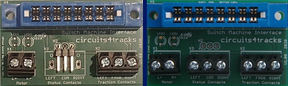 | | Specifications: | | Version: | 1.00 | | Card size: | 2.154" x 1.324" | | Motor power connector: | 2-position terminal block
Each terminal accepts 14-22 gauge wire | | Traction/track contacts (Pins 2, 3, and 4): | 3-position terminal block
Each terminal accepts 14-22 gauge wire | | Status/aux contacts (Pins 5, 6, and 7): | 3-pin header OR 3-position terminal block
For terminal block, each terminal accepts 14-22 gauge wire | | Other features: | Reversible
LED motor indicators | | Options: | LED Colour:
Left yellow/right green
Left green/right yellow | | Approximate kit assembly time: | 5 - 10 minutes |
|
Signal Animator
New version 1.10 circuit boards are now in stock and kits and units will be available within the next few days. Note: SGA prices have DECREASED.
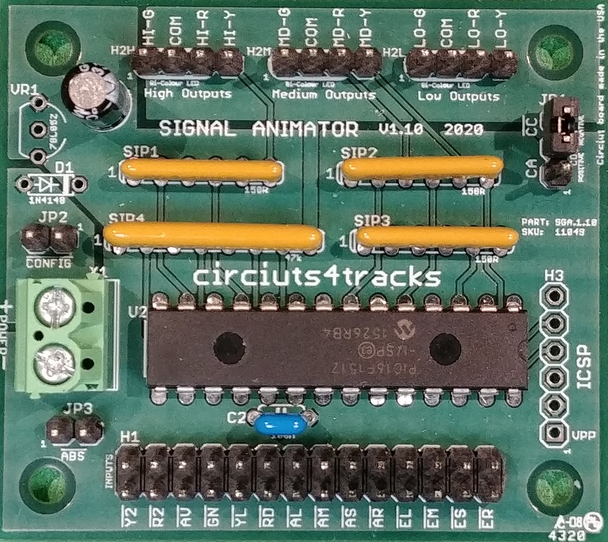 | | Specifications: | | Version: | 1.10 | | Card size: | 2.25" x 2.00" | | Mounting hole size: | 0.125"
Suitable for #4 screws | | Power supply requirements: | Versions for 5 VDC (standard) or 8-16 VDC (special order)
1-2 mA minimum (dark indication)
Plus 10-20 mA per LED illuminated | | Output mode: | 3-output Type D: R/Y/G for each head - changes have brief dark moment.
2-output Type SA: R/G for each head (both provide Y) - changes between G and Y have red "flicker"
3-output Type SA: R/Y/G for each head - changes between G and Y have red "flicker" | | Input connector: | 2x14 header, 0.1"/2.54 mm spacing | | Output connectors: | 1x4 header for each signal head (high, medium, low), 0.1"/2.54 mm spacing
4-position mini terminal blocks available by special order | | Selectable output common: | Jumper to select either common-anode (+) or common-cathode (-) LED configuration | | Dual occupancy inputs: | Occupancy inputs may use either two inputs (R-G) or three inputs (R-Y-G) - no jumper selection needed.
With two inputs, approach indication is conveyed when both red and green are active. | | ABS operation mode: | Jumper to enable basic ABS signalling logic to be performed on-board. | | Input for "Advance
Clear To" indications: | CROR Rules 412, 413, 414, and 415 implemented.
All these indications all have a flashing high head aspect. | | Animation: | Type SA: changes between green and yellow have a brief red "flicker". See video
Type D: all changes have a brief dark moment | | ROHS compliant: | Yes | | Approximate kit assembly time: | 30 - 45 minutes |
|
Grade Crossing Controller
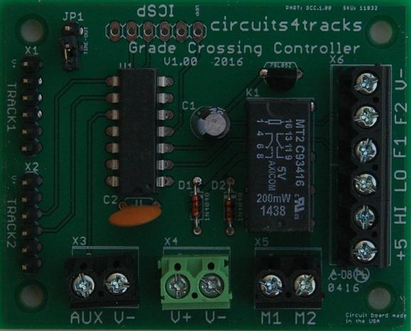 | | Specifications: | | Version: | 1.00 | | Card size: | 2.50" x 2.00" | | Mounting hole size: | 0.125"
Suitable for #4 screws | | Detector inputs: | 3 detectors per track
Inputs for two tracks provided.
Additional tracks supported with additional GCC units. | | Power supply: | 8-16 volts DC
Less than 100 mA, depending on output load | | Outputs available: | 1 active high (+5 volts when activated)
1 active low (0 volts when activated)
2 alternating at 1 Hz rate
2 that switch between V+ and V- when activated or deactivated - suitable for driving a stall-motor device | | Output connectors: | Screw terminal blocks | | ROHS compliant: | Yes | | Approximate kit assembly time: | 25 - 30 minutes |
|
The Traverser
Available for both linear and loop operation.
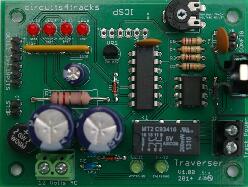 | | Specifications: | | Version: | 1.00 | | Card size: | 3.00" x 2.25" | | Mounting hole size: | 0.125"
Suitable for #4 screws | | Power supply requirements: | 12 volts AC, up to 1 ampere. | | Input power connector: | Screw terminals.
Each terminal accepts 14-22 gauge wire | | Detection input connector: | 6-pin SIP header.
Identical to the output connector on our Quad Occupancy Detector | | Detection inputs: | Four active-low inputs.
Two for each end of track, two for each end's approach block | | Other input: | One active low input to hold train at next stop. | | Track power connector: | Screw terminals.
Each terminal accepts 14-22 gauge wire | | Maximum track output voltage: | Adjustable from 6.5 volts to 11.0 volts (DC). | | Maximum track current: | 1 ampere.
Actual maximum is limited to the capabilities of the 12 volt AC supply used | | Stop duration: | Default of 2 seconds.
Other configurable choices: 5, 10, 15, 20, 30, 45, 60, 75, 90, 120, 150, 180, 210, 240, or 255 seconds | | ROHS compliant: | Yes | | Approximate kit assembly time: | 45 - 60 minutes |
|
Fast Clock Display
For use with NCE DCC Systems
Can be used for real time by configuring command station with fast clock ratio of 1
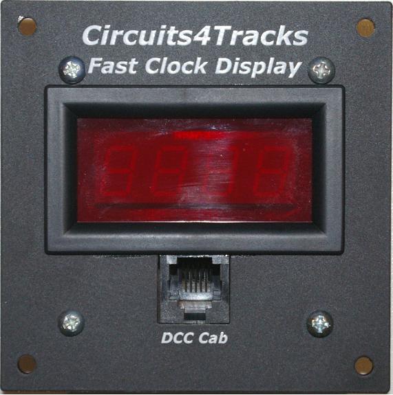 | | Specifications: | | Version: | 1.00 | | Card size: | 2.30" x 2.30" | | Mounting hole size: | 0.125"
Suitable for #4 screws | | Hardware: | 3.00" x 3.00" powder coated aluminium panel for fascia mounting.
0.125" mounting holes. Suitable for #4 screws | | Power supply requirements: | May be powered from cab bus or separate AC adapter. Current draw under 20 mA. | | Display: | 7-segment LED display. 4 digits; Red 0.4" high. | | Display Format: | Time is displayed in 12- or 24-hour format, as configured by the NCE command station
In 12-hour format, PM is indicated by blinking colon | | Cab bus connections: | Two rear RJ-14 connectors for in-line bus connection,
One front panel RJ-14 connector for cab connection. | | Included feature: | Time/temperature function for on-layout display sign.
Requires small display, not yet available | | ROHS compliant: | Yes | | Approximate kit assembly time: | 25 - 35 minutes |
|
Accessories
Accessories for use with other products.
Signal Master Plus
This is the product family of our Computerized Signalling System that is currently under development.
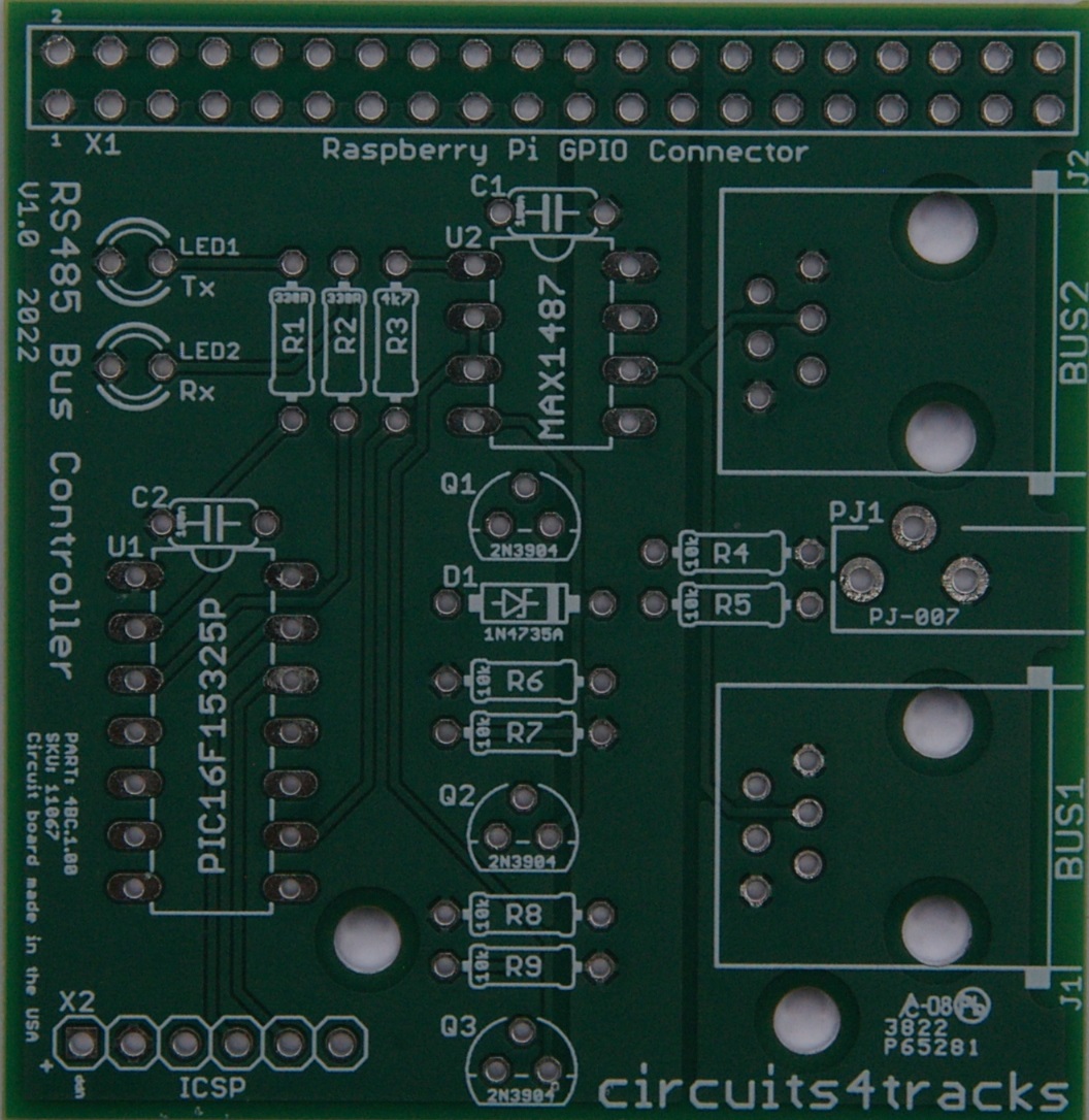 | | Specifications: | | Component name and version: | RS-485 Bus Controller V1.00 | | Card size: | 2 5/32" x 2 3/32" | | System requires: | Only one of this card | | : | | Component name and version: | Discrete I/O Card (10 In/12 Out) | | Card size: | 2" x 2 13/16" (fits 70 mm DIN rail carrier) | | System requires: | One or more, depending on I/O needs (maximum 127) | | Input connectors: | 10 inputs:
Five 1x3 headers with 2 inputs and ground
Two 1x6 headers with 4 inputs, ground, 5 VDC (matches QOD) | | Output connectors: | 12 outputs:
Three 2x4 headers with 4 outputs and V+ |
|