


The ability to have signals with speed indications can involve a daunting circuit if performed in hardware. Software drastically simplifies this, but requires a significant number of outputs. Add to this is the choice of signal styles: 3-colour versus searchlight and the way to wire them: common positive or negative.
We have designed a signal driver around a PIC microcontroller to get the best of both worlds. The Signal Animator does all this with the flexibility of being usable for searchlight and three-colour signals, wired common positive or negative. As a background to this design, here are some references regarding signalling:
This article describes the patterns and non-patterns in CROR signal indications. Originally appearing in the February/March 1994 issue of Rail and Transit (the newsletter of the Upper Canada Railway Society), this article has recently been updated to reflect new signal indications in the latest revision of the CROR.
This is the latest revision of the Canadian Rail Operating Rules, effective June 24, 2020, published by the Railway Association of Canada.
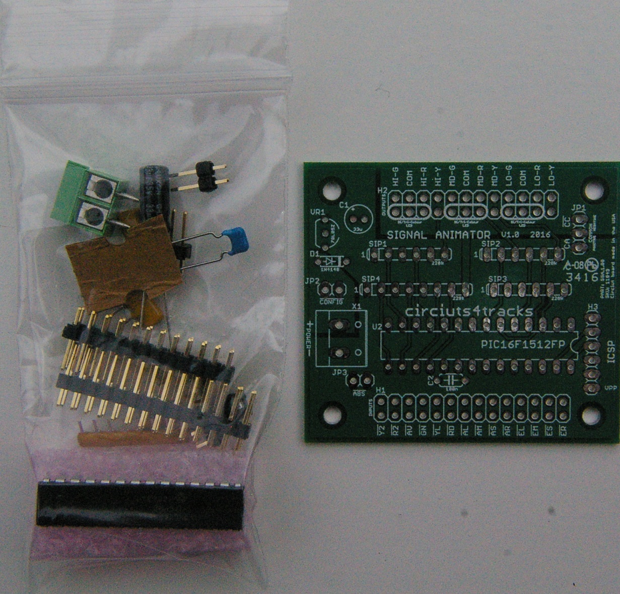 Price: $13.99 Signal Animator, 5 VDCBoard & Parts Kit to assemble one Signal Animator. Powered by 5 VDC regulated. This item can be shipped within 2-3 business days. | 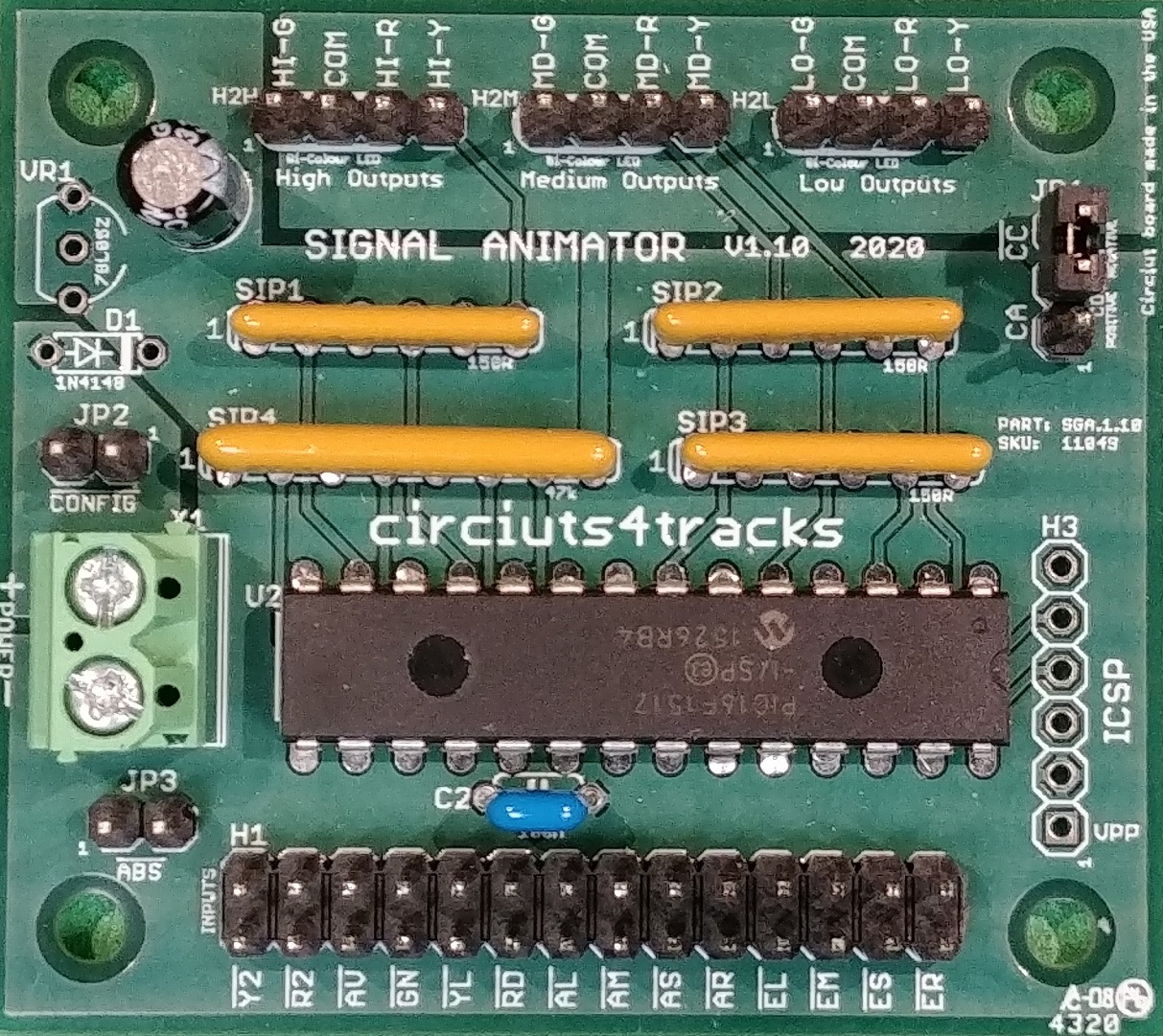 Price: $21.99 Signal Animator, 5 VDCAssembled and tested Signal Animator. Powered by 5 VDC regulated. This item can be shipped within 2-3 business days. |
 Price: $8.09 Signal AnimatorEmpty circuit board for one Signal Animator. 38 available for immediate shipment. | 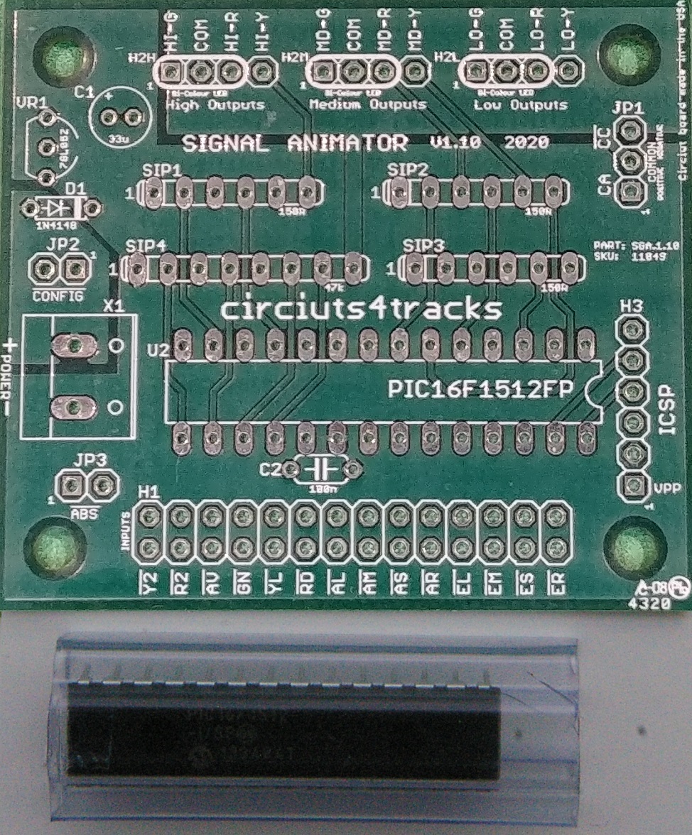 Price: $10.79 Signal AnimatorWhen ordering, you will be sent an email to indicate what default mode software version you want. This is only the default, you can always reconfigure the mode. This item can be shipped within 2-3 business days. |
The Signal Animator version 1.10 is now available. There are some minor changes coming to the product.
Software
There is a new version of the software. SGAs sold since 29-Jan-2017 had version 2.00, but the current release is now 3.11, 3.12, or 3.13 (see below) which has the following changes:
- Bug Fix: type SA aspects changing between green and yellow (either direction) only showed the red flicker when both the old and new indications were solid; the fix now provides animated flicker when either the new, old, or both indications are flashing (Note: this affects very few indication changes)
- Version Indication: on power-up, the high and low signal head outputs blink the version number in red before normal operation commences.
Three versions of software are now available, with the difference being the default operating mode. You can always reconfigure the operating mode at any time, but if you use a particular mode, you can receive your SGAs ready to use without the need to reconfigure:
- 3.11: For type SA signals using two-colour LEDs - this used to be the default for all SGAs
- 3.12: For type SA signals using three-colour LEDs
- 3.13: For type D signals
The software hex image on the SGA Documentation Page has version 3.11 available. If you have older SGAs but do not have the ability to flash the software, email us to find out if you need the update and how it can be arranged.
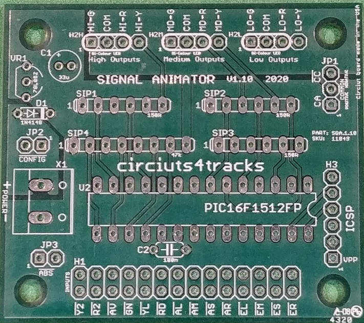
Circuit Board Layout
The version 1.10 SGA boards have a few layout changes. Overall dimensions and the mounting hole locations remain exactly the same. The changes are:
- Output Connections: The former use of a 2x12 header has been replaced with three 1x4 headers. The new layout puts a small space between the connector for each signal head, and more space from other components, making it easier to connect signal wiring. The new headers maintain the exact same pin order that was used on the old header (Grn-Com-Red-Yel). It was found that using a separate connector for each signal head was more practical for installation of the signal appliance on a layout, and providing a little space between them made it easier to connect them.
- 5 Volt Version: only the version that requires a regulated 5-volt power supply will be our standard product, as this was most popular. The circuit board will still have provision for the unregulated (8-16 VDC) power version, but these are special order and will take a couple of extra days to ship. For assembling kits, it will no longer be necessary to add two solder bridges for the 5 volt version. Instead, traces provide the bridges and if assembling the unregulated power version, the bridge traces will have to be cut.
- Common Anode/Cathode Jumper: there is more space between this jumper and surrounding components, making it easier to get to if changing our performing a reconfiguration.
|
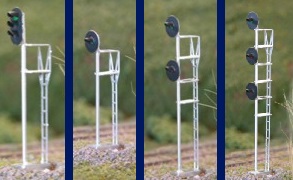
Circuits4Tracks only makes the electronics for signalling, we do not make the wayside signal appliances. The Signal Animator has the flexibility of being able to drive either Type D (3 separate LEDs) signals or Type SA Searchlights (using either Red/Green, or Red/Yellow/Green LEDs), wired with either common anode or common cathode. Various manufacturers of signals exist. One option is to purchase dummy signals and add your own LEDs and a company that makes signals for HO and N scales is Pro Tech Model Parts. |
|
|
Delivery options:
|
Payment methods available:
|
 Canada: $14.00 (tracked)
 USA: $35.00 (tracked)
 Australia: $40.00 (tracked)
 UK: $30.00 (tracked)
 EU: $26.00 (tracked)
 Thailand: $40.00 (tracked)
 UAE: $40.00 (tracked)
 Other locations: $40.00 (tracked where available)