


The cornerstone product of Circuits4Tracks is our Quad Occupancy Detector (QOD). This is an important part of a signalling system, but it is not the only part (see our article on The Signalling Process).
Another product we have is the Signal Animator (SGA). This product serves as a driver for a signal appliance that takes speed restriction logic away from the main signal logic processing. The SGA has a mode of operation that provides simple Automatic Block Signalling directly from Occupancy Detectors. Though it is for simple applicaitons, it does involve a fair bit of interconnections between detectors and SGAs.
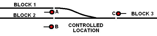
What is done at an interlocking? Sometimes called a Controlled Location, Control Point, or O/S Section, the signals at an interlocking must also use inputs indicating switch positions. Furthermore, the occupancy of signal blocks overlap within the interlocking. Consider the diagram to the right. The occupancy of Block 3 always includes the occupancy of the Controlled Location. However, the occupancy of Block 1 and Block 2 will only include the occupancy of the Controlled Location when the switch is aligned for the block in question. Signal A guards entry into Block 3, but must be red if the switch is aligned for the straight route. Signal B guards entry into Block 3, but must be red if the switch is aligned for the diverging route. Signal C may guard entry into either Block 1 or Block 2, depending on the switch position.
This increases the complication of the interconnecting wiring, and we haven't even touched on whether this Controlled Location is under CTC or Absolute Permissive Block operation!
Circuits4Tracks is owned by a model railroader who has been in the process of building a layout since 2008 with a full computer-based signalling system. An early version of the QOD is used for block detection, and signals are driven by a predecessor of the SGA. We would like to market the part of this system that processes the signalling logic, but a newer generation of hardware will be needed. The experience with this system over the past nine years has provided a good foundation for the specifications and initial design for a marketable system.
This article describes the system as it currently exists and outlines its features and benefits. This is followed by outlining the issues that make the current system difficult, if not impossible, to market to the general public. Finally, the specifications and initial design choices for a new generation system is described.
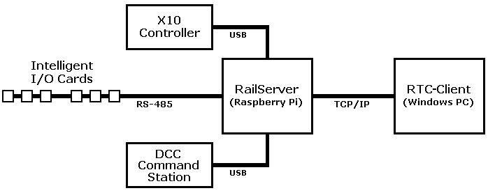
The components of the current system are shown in the diagram below. RailServer and RTC-Client may run on either separate computers or on the same computer:
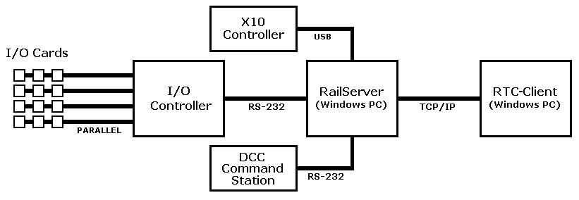
The current system makes use of two or three computer systems that work together, along with a DCC command station and an optional X10 controller for control of room lighting.
The first computer system is a custom-designed embedded system that interfaces with the layout. This is called the I/O Controller. "I/O" stands for Input/Output, and its job is to read inputs and report changes over a serial (RS-232) interface, while accepting commands to change outputs and carry out those changes. This system uses I/O cards that provide 8 inputs and 10 outputs that connect to the main controller over a parallel bus comprised of a 20 conductor ribbon cable. A bus can have up to 16 I/O cards on it, and four buses available. This allows up to 64 I/O cards, plus there is another I/O card built into the main controller that provides a full 8 inputs, but only 6 outputs.
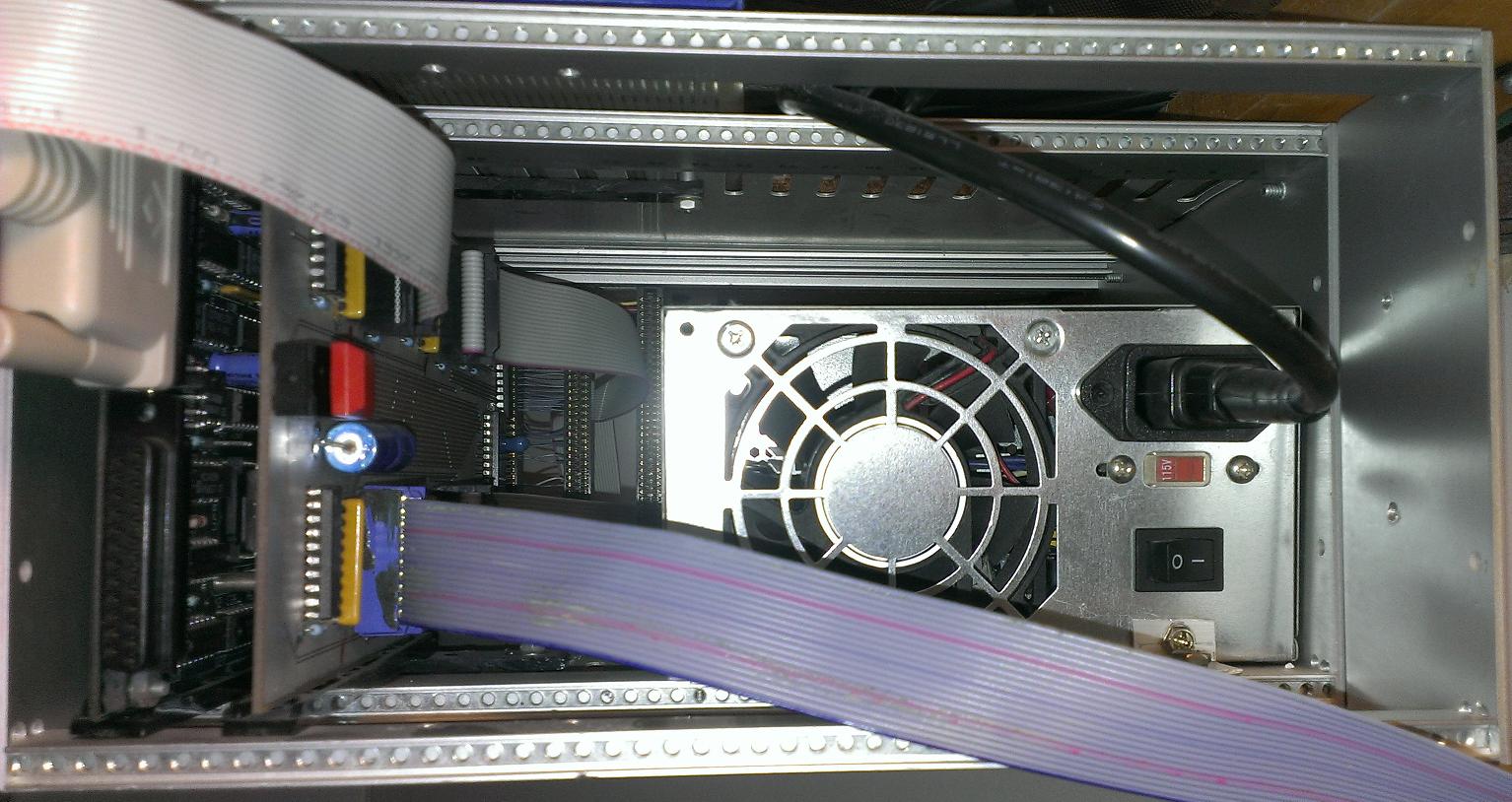
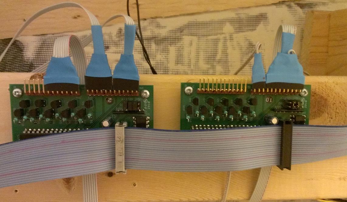
CPU Card on far left with bus interface card
next to it.
Inputs are driven by switch machine contacts, push buttons, and the QOD. Outputs are open-collector, which allow powering items of varying DC voltages, but to simplify things only a 5-volt power bus is used to power building lighting and wayside signals. The I/O Controller scans inputs and provides debouncing to confirm that an input has changed state, then reports the change over an RS-232 connection to a Windows PC running an application called RailServer.
This application runs on a Windows PC and is the heart of the system. It is configured to know the topology of the layout. That is, knowing about blocks and switches, and what other blocks and switches are neighbours to them. RailServer is also configured to know what signals exist and what block each is associated with.
Two other objects that may be used, though not related to layout topology, are Devices and Requests. Devices are objects that have an on/off status and may be configured to be tied to one or more outputs. This provides a way to control things on the layout such as building lighting, street lamps, or animated devices. A Request is tied to an input and may be used to initiate an action, such as throwing a switch, executing a DCC macro, or requesting local control of a switch from the Rail Traffic Controller (dispatcher).
Signals are configured to use either two or three outputs for display purposes. Devices may be configured to use one or more outputs to control something on the layout. When RailServer's processing determines that an output must change because of a state change of a Signal or Device, it sends commands to the I/O Controller to request the change. Once the I/O Controller completes the change, it will let RailServer know.
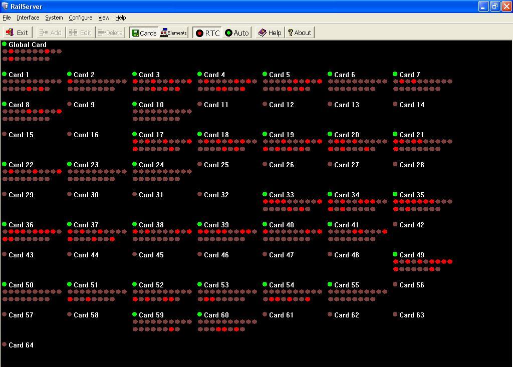
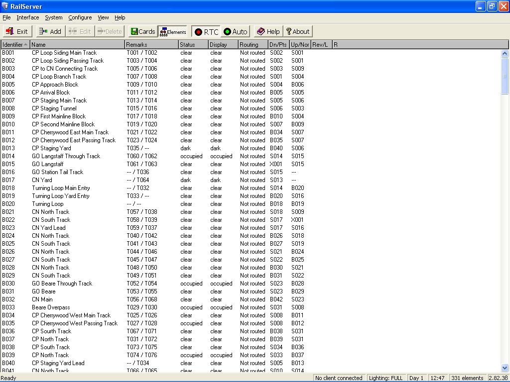
RailServer has the configuration about the layout, including how to display it, but it does not have a graphical display interface of the layout. It only provides information on objects in a table format (above right image), or a graphical view of I/O cards (left image) for troubleshooting.
Operation may be fully automatic, where all signals operate in ABS mode, or require a Rail Traffic Controller (RTC, also sometimes called a dispatcher) to clear signals at controlled locations through an interface using another application called RTC-Client.
RailServer maintains a configurable fast clock. Fast clock time is used to control room lighting (if used) and devices configured to operate based on time of day. The fast clock value is periodically sent to the DCC system (if it has a fast clock feature) to keep it synchronized.
This application runs on a Windows PC and provides a graphical interface of the layout, showing the track diagram with colour status. Track switches may be thrown, if a route has not been cleared through them, by clicking on a switch on the diagram, which sends a request to RailServer which in turns sends the appropriate command to the DCC command station to throw the switch. Contacts on the switch machine provide feedback through the I/O Controller that update the state of the switch in RailServer and change the display in RTC-Client to show the new position of the switch.
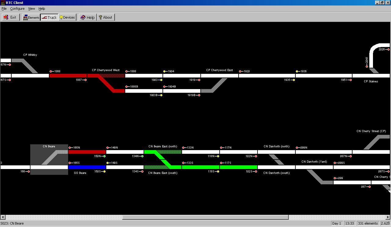
Track on RTC-Client's display is normally shown in white. When a route is reserved by clicking on the home signal at the entry to the route, all track on the route up to the next home signal will be displayed in green to indicate the reservation. As a train moves through the route, a section will change to red while it is occupied and return to white once it is no longer occupied.
The Rail Traffic Controller may also issue Track Occupancy Permits (TOP) to block out parts of the line from normal routing. When a section of track is under a TOP, it is displayed in blue. Local control pushbuttons for switches, which are usually locked out from use, are enabled when the section of track is under a TOP.
RTC-Client may run on the same computer that RailServer is running on. As it runs as a separate program that communicates with RailServer using TCP/IP, it may also run on a separate computer that has a network connection to the RailServer computer. With the proper router setup, RTC-Client can connect to RailServer over the Internet from anywhere there is access to the Internet.
A number of issues with the current system make it impractical to market. The first two are with the I/O Controller. The Controller itself uses a proprietary CPU card that is somewhat expensive and requires a special card cage to house it. In addition to this, the use of a parallel bus to connect to I/O cards located around the layout has problems with distances over 30 feet due to electrical noise.
The next issues are related to the I/O cards. The current cards make use of 6821 PIA chips that are now over 40 years old and are becoming difficult to obtain. Furthermore, these chips are in a 40-pin DIP package that requires a lot of space for only 18 I/O lines. Newer products can provide the same number or more I/O lines in less than half the space. Though not a great limitation except for very large layouts, the parallel bus system only supports 64 I/O cards (plus the one on the Controller), and they all must be identical (same number of inputs and outputs). As there is no intelligence on the I/O cards, a jumper block is required to configure each I/O card with its unique address.
Finally, for some model railroaders the need for a computer to run RailServer is a significant issue. While the use of a computer for running RTC-Client is necessary, anyone wanting a system that runs automatically without the need to have a dispatcher that uses RTC-Client may not want to dedicate a computer just for performing the tasks of RailServer. By "dedicate", the RailServer computer needs to be connected to the I/O Controller, the DCC system, and the X-10 controller. If one only has a laptop available, connecting and unconnecting all of this can be a pain. Using a laptop for RTC-Client does not have this issue since its connection is through a network, which can be a Wifi connection.
By placing some intelligence on an I/O card using micro controller technology, several benefits will be achieved. First, it will be possible to have an I/O card with an increase of I/O connections. At this time, we are looking at using the same micro controller we use for our SGA for our initial I/O card. This will have around a dozen outputs and a dozen inputs. In the future, it will be possible to develop new I/O Cards with a different configuration of inputs and outputs, including Analog-to-Digital (A/D) inputs and Digital-to-Analog (D/A) outputs.
Second, the I/O card will perform debouncing of inputs on the card, and it will transfer information via an RS-485 serial bus. This type of bus allows greater distances without the noise problems associated with a parallel bus. The bus is expected to be wired using a four-wire RJ-12 connectors, similar to the way some DCC systems have their cab bus wired, making it easy to hook up.
Instead of using jumpers, the intelligence on the I/O cards will also allow a soft configuration of each card's address the way that the address of a DCC decoder may be changed. While RS-485 is designed for 32 unit loads, using new generation transceiver chips that are only a quarter unit load, the bus will support 128 devices (including the master device for the bus).
A new system will combine the functions of the I/O Controller (except debouncing, which will be done on the cards) with the computer running RailServer into a small single-board computer. Several small single-board computers are on the market with prices as low as about $40. This computer would need an RS-485 interface to communicate with the intelligent I/O cards, along with USB ports for connection to a DCC command station and an optional X10 controller. For configuration purposes, it would be necessary to connect a keyboard and monitor, and possibly a mouse, but these would not be needed for regular operation. An ethernet port would be needed in order to use RTC-Client. With internet access, automatic updates could also be supported.
We are currently looking at using a Raspberry Pi computer for this purpose as they use the Linux operating system and porting of the RailServer software from Windows to Linux is very feasible.
RTC-Client would remain unchanged and would continue to run on a Windows PC.
RS-485 is not the easiest task for a Raspberry Pi. The serial ports on the microcontrollers we use support a 9-bit message format that greatly simplifies an RS-485 interface, but the serial port on a Raspberry Pi does not. Additionally, the extra task of managing the RS-485 communications is an extra burden for RailServer to deal with.
The solution to this is to develop an RS-485 bus master that has two serial ports and enough RAM to buffer information. One port will be used as the master of the RS-485 bus, polling I/O cards to send commands and buffer updated information from the cards, and the other port would be used to communicate with the Raspberry Pi using the exact same commands that RailServer currently uses to communicate with the I/O Controller. The microcontroller needed for this task must have two serial ports and only one discrete output for selecting transmit and receive for the RS-485 bus. In theory, that should be possible in an 8-pin package, but at the start of 2016 the smallest microcontroller with two serial ports had 64 pins. Smaller units were in the works, but only defined as a "future product".
By the end of 2016, a number of the new microcontrollers became available, and the decision to go with one that comes in a 14-pin package is ideal. This "bus master" device will be designed as a daughter board that plugs onto the header plug of the Raspberry Pi, and it will have a pair of RJ-12 jacks for attaching to a bus. Two jacks will be provided for installing the master at any point on the bus that is not at an end where only one jack will be needed.
Design of the master and the initial I/O card are underway and future developments will be added here. Feel free to email us with any comments or questions regarding this project.