


This article describes the process of implementing a working signalling system. It describes the basic blocks that make up the whole system and how they function together. This article does not go into the details of signal indications, what they mean, and the rules surrounding signal indications. For more information on that, consider the following:
This article describes the patterns and non-patterns in CROR (Canadian Rail Operating Rules) signal indications. Originally appearing in the February/March 1994 issue of Rail and Transit (the newsletter of the Upper Canada Railway Society), this article has recently been updated to reflect new signal indications in the latest revision of the CROR.
This is the latest revision of the CROR, effective May 28, 2008, published by the Railway Association of Canada.
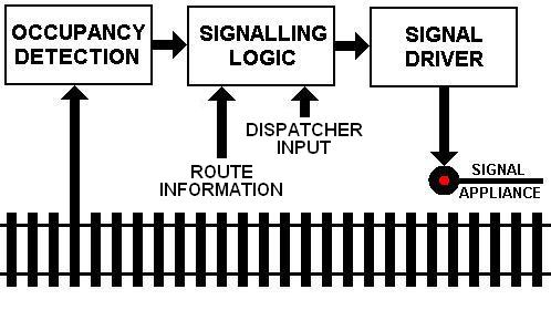
A signalling system comprises four components as shown the figure to the right: occupancy detection, signalling logic, signal driver, and the signal appliance. Depending on the implementation, some of these components may be combined.
Occupancy Detection
Signalling systems begin with Occupancy Detection. Information on whether each block of track is occupied or not is needed for processing by the Signalling Logic. Detection can be done in one of two basic ways: point detection and whole block detection. Point detection is useful when it is necessary to know that a train has reached or cleared some point, but for signalling systems it is necessary to use whole block detection, where a train located at any place within a block results in the whole block being considered as occupied.
The Quad Occupancy Detector by Circuits4Tracks provides whole block detection that is ideal for a signalling system.
Signalling Logic
The Signalling Logic is where everything happens with a signalling system. If a single track were to be signalled for automatic block signals, then the logic needs only Occupancy Detection information. The red output for a signal must be active if the block who's entry is guarded by that signal is occupied. If the block is not occupied, then the yellow output must be active if the logic has the next signal down the line displaying red, or the green output must be active if the next signal down the line is not displaying red.
Where track switches exist, their position is used as Route Information by the Signalling Logic in order to figure out what the next block down the line is. With the next block determined, the rest of the logic applies in most cases. Track routing may involve speed restrictions that are reflected in signal indications. While it is possible to have the Signalling Logic deal with speed restriction indications, it is an unnecessary complication to the logic that requires an extra degree of configuration (that is, allowing the logic to know what the restrictions are for each situation). Taking route information and turning it into a speed-limit indications is best left to the Signal Driver part of the process.
Keeping the use of Route Information to only determine the next block, and have the Signalling Logic provide basic red-yellow-green block indications keeps the Signalling Logic as simple as possible.
One other source of input that the Signalling Logic may need is that of Dispatcher Input. At controlled locations, such as where sidings begin or end, where cross-overs between main tracks are, or where lines cross at grade, the signals do not automatically clear after a train passes. Instead, they remain at red until someone, the Dispatcher, clears a route through the location. The logic that provides this human input should be implemented to prevent such operations to occur when the track through the location is occupied.
One way to implement Signalling logic is through the use of a software-programmable system, such as a personal computer. Due to its complexity, at this time, Circuits4Tracks does not have a product to provide this part of the process.
Signal Driver
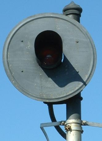
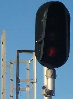
Type SA signal Type D signal Depending on the outputs available from the Signalling Logic and the type of illumination device used, this can vary from a very basic circuit to something a little more complex.
For example, if the Signalling Logic provides two outputs, one active for green and one active for red (and both active for yellow) and is needed to drive a Type SA (see photo far left) signal that is illuminated with a tri-colour LED, then only a pair of current-limiting resistors are needed.
Similarly, if the Signalling Logic provides three outputs (red, yellow, and green) intended for a Type D (see photo near left) signal using single colour LEDs, then only three current-limiting resistors are needed.
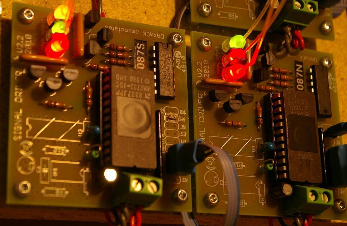
Signal drivers with LED indicators on-board.
Fiber optics take the light to the appliance.However, if the two outputs are used with a Type D signal, the driver must implement some logic that lights the yellow light while shutting off the red and green lights when both the red and green outputs are active. A similar situation exists when three outputs are used with a tri-colour LED.
All this does not take into account any speed-limit indications. If the Signalling Logic takes switch positions as input and provides outputs for each head on the Signal Appliance, then the Signal Driver may be simple. However, including speed-limit information in the Signalling Logic is unnecessarily complicated and is output intensive. Nine outputs are needed for a three-head appliance of Type D signals. For this reason, it is better to have the Signalling Logic deal with only the basic block occupancy indication (red, yellow, or green) and have the Signal Driver turn this into a speed-limit indication where needed.
Added to this, some speed limit indications make use of flashing aspects and this also adds complexity that would be better implemented on a Signal Driver.
Circuits4Tracks is in the final design stage for a microcontroller-based signal driver called the Signal Animator. Watch our Products Page for information on this product.
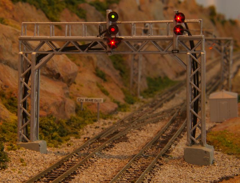
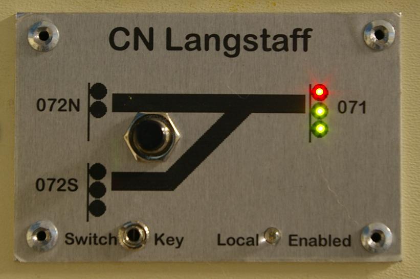
Signal Appliance
This is the actual scale model line side signal such as the one in the photo to the left. In some situations, where an installed signal model cannot be seen properly by an operator, it may be indications on a fascia-mounted panel such as the one in the photo to the right.
With either implementation, each signal head requires an illumination device or devices, which could be an incandescent bulb or an LED. In the case of a Type D signal, one illumination device per colour used is needed.
Where size is a concern, it may be possible to install the illumination device away from the Signal Appliance, perhaps on the circuit board of the Signal Driver, and use fiber optics to deliver the light to the appliance.