Product Documentation
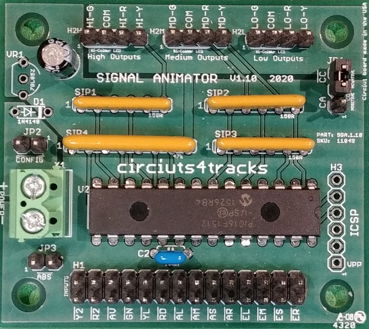
Signal Animator

Documentation:

Articles and Application Notes:

Specifications:
Version:1.10
Card size:2.25" x 2.00"
Mounting hole size:0.125"
Suitable for #4 screws
Power supply requirements:Versions for 5 VDC (standard) or 8-16 VDC (special order)
1-2 mA minimum (dark indication)
Plus 10-20 mA per LED illuminated
Output mode:3-output Type D: R/Y/G for each head - changes have brief dark moment.
2-output Type SA: R/G for each head (both provide Y) - changes between G and Y have red "flicker"
3-output Type SA: R/Y/G for each head - changes between G and Y have red "flicker"
Input connector:2x14 header, 0.1"/2.54 mm spacing
Output connectors:1x4 header for each signal head (high, medium, low), 0.1"/2.54 mm spacing
4-position mini terminal blocks available by special order
Selectable output common:Jumper to select either common-anode (+) or common-cathode (-) LED configuration
Dual occupancy inputs:Occupancy inputs may use either two inputs (R-G) or three inputs (R-Y-G) - no jumper selection needed.
With two inputs, approach indication is conveyed when both red and green are active.
ABS operation mode:Jumper to enable basic ABS signalling logic to be performed on-board.
Input for "Advance
Clear To" indications:
CROR Rules 412, 413, 414, and 415 implemented.
All these indications all have a flashing high head aspect.
Animation:Type SA: changes between green and yellow have a brief red "flicker". See video
Type D: all changes have a brief dark moment
ROHS compliant:Yes
Approximate kit assembly time:30 - 45 minutes

Archived Documentation (for discontinued versions):