


Railway signalling has two main functions. The first is to keep trains a safe distance apart, and the second is to ensure safe movement through places where tracks intersect or branch. This article provides a brief historical background of signalling and moves into a description of typical signal placement for the benefit of model railroad signalling.
Early Days
Early railway operation used timetable schedules with station locations used for meeting points for trains going opposite directions. Trains following other trains were permitted to pass a station only after a minimum amount of time had passed. This meant signalling was a manual process involving a person who manually cleared an indication permitting a train to pass to the next station. From these early days, signals needed to convey two indications: danger and permissive (or clear).
In the earliest days, there was no knowledge of when a train arrived at the next station. If a train was waiting to meet an oncoming train, there was no way of knowing if it was running late. The invention of the telegraph around 1840 overcame this problem in the UK, but its use in North America did not take root until the early 1860s. Even with the telegraph, signals remained manually operated and usually only one train occupied the entire distance between stations.
In some cases, a following train was permitted to proceed behind another between stations, but if the leading train needed to make an unscheduled stop, a crew member had to provide protection by walking a mile or more behind the train to place something to indicate to a following train that they were stopped ahead. Early trains travelled at low speeds, but needed over a mile to stop. As brakes were placed on all cars of a train stopping distance was reduced, but the need to manually apply brakes one car at a time along with advances in propulsion meant that stopping distances remained long. Even with the introduction of air brakes in the late 1860s, train speed continued to keep pace and stopping distance was similar to earlier trains.
Trains would have to reduce speed on approach to stations in case a stop was necessary. To improve speed where a stop would not be necessary, some form of advance information about whether or not a stop was needed could be used. With manual operation, it required someone to ride out on horseback to change this "distant" or "advance" signal.
The Age of Automatic Block Signalling
It was not until 1872 that William Robinson invented and developed a closed track circuit that could automatically detect the presence of a train in a section of track. The "closed" design made it the first such circuit that was fail-safe, meaning the circuit had to prove a section of track was unoccupied. If anything failed in the circuit, it couldn't prove unoccupancy and the track would be treated as occupied, failing in the safest state.
With an automatic way of determining if a train was in a section of track, it was no longer necessary to reserve the entire space between stations for one train. The track could be divided into several sections, called blocks, that only needed to be long enough to bring a train to a stop. Entry to a block would be protected by an automatic signal that would indicate danger if the block were occupied and permissive if unoccupied.
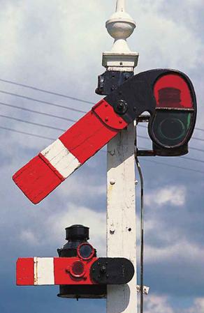
Lower quadrant semaphore signal. Upper head indicates this signal may be passed, and lower head indicated the next signal may not be passed.How an indication is displayed is called its aspect. Today, a danger indication is conveyed with a red light aspect. Earlier signals would use a semaphore blade in a horizontal position. Since there were only two indications initially, the earliest signals used only two aspects: one for the danger indication, and one for the permissive indication. These signals were known as lower-quadrant semaphores, where the permissive aspect had the blade point downwards at about a 45 degree angle.
In order to give a train crew advance knowledge of an upcoming stop signal, two-aspect signals would use two units mounted on the same mast. The upper one protected entry into the block, and was called the "running" or "stop" signal. The lower one provided advance indication of what the signal in advance was displaying (i.e. the next signal down the line).
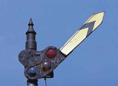
Later, three-aspect signals gained in popularity, and advance notice of an upcoming signal at danger could be conveyed with a single semaphore arm. Initially, this was implemented using upper-quadrant type semaphores showing a horizontal position for danger, a vertical position for the most permissive indication, and an upwards 45 degree position for the permissive indication that conveyed the upcoming signal at danger, known as an "approach" indication.
Upper quadrant semaphore signal. This signal is displaying the same indication as the lower quadrant signal above.Though colour light signals were not well adopted until the early 1900s, semaphores made use of colour glass roundels in front of a kerosene lamp for night time visibility. While red has always been used for stop or danger, prior to about 1890, white was used for permissive (clear) indications. For three-aspect signals, green was the colour used for approach. It wasn't until almost 1908 that most railways had adopted the familiar red-yellow-green sequence we know today.
Generally speaking, Automatic Block Signalling (ABS) signals are permissive. This means a signal may be passed when displaying its most restrictive indication, but only at restricting speed until it reaches a signal displaying a less restrictive indication. In some cases, the indication is Stop and Proceed, meaning the train must first make a full stop before continuing at restricting speed. In other cases, the indication is Restricting and may be passed at restricting speed without first making a full stop. In both cases, restricting speed is a speed that permits stopping in only half the distance of visibility, but at no times faster than 15 miles per hour.
The Interlocking
As previously mentioned, one function for the stations in the early days of railways was to provide a way for trains moving in opposite directions to meet each other. The simplest station would have a passing siding with a turnout at one or both ends. The turnout or turnouts would be controlled to allow a train to take the siding or remain on the main track. Early on, it became important to use signals to indicate to a train crew if they were to be taking a siding or staying on the main track.
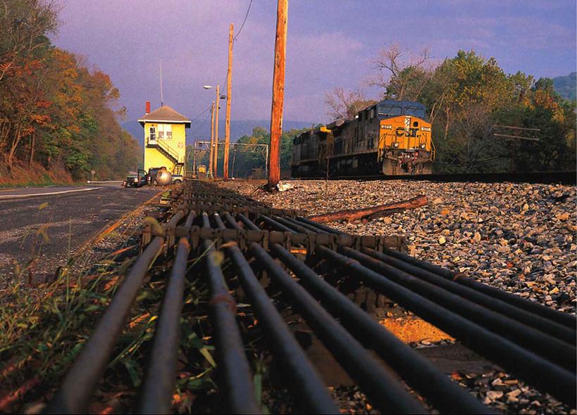
Mechanical interlocking.Operating the signals and the turnouts was the task of the person at the station, and running around to throw points and clear signals was not an easy task, especially in inclement weather. Being able to do that indoors lead to some complex mechanical arrangements of levers, pipes, and chains. For safety reasons, it became necessary to connect the operation of turnouts with that of signals. It was important to not allow a signal to display a permissive indication if a turnout was not aligned properly, or if the track is aligned for another train that has been given a permissive signal.
Tying together, or interlocking, the operation of the turnout controls with the signal controls was first used in the UK when John Saxby received the first patent for interlocking switches and signals in 1856. Since these signals are interlocked to a route when it is safe to pass, the most restrictive indication an interlocking signal must display is Stop and Stay, or simply Stop.
Another difference in the function of interlocking signals is that they must convey more information than a permissive/danger indication based on occupancy status. Depending on the rules that apply, interlocking signals may convey either route information or speed restriction information about the route through the interlocked area, also known as the interlocking plant, or simply interlocking. This additional information is not a requirement for most ABS signals, though when speed indications are used, the final ABS signal before an interlocking provides advance information about the speed indication at the interlocking. These final ABS signals are usually called "advance" or "distant" signals.
Centralized Traffic Control
Instead of having each interlocking controlled locally, CTC moves the control of many interlockings to a single control centre. Between interlockings, ABS signalling is used and the central control location has no control over the ABS signalling, in the sense that it cannot force an ABS signal to remain at its most restrictive indication.
A speed restriction in a route through an interlocking will affect the indication is displayed at a distant signal, but this is an indirect result of what is controlled centrally under CTC.
Where Are ABS Signals Placed?
ABS signals are the easiest to place, as there are few restrictions on their placement. On the prototype, ABS signal placement is based on stopping distances for trains. On model railroads, this tends to be less of a concern, though if some form of momentum is used on cabs or configured on a DCC system, it may have an effect on signal placement. Block lengths on model railroads tend to be related to train lengths, as distance compression is often used to simulate greater distances between stations.
Actual location of signals should take into account sighting distances. Ask yourself, if you could actually be in the cab of a model train, how far away from a signal will the train be when you can first see and identify the aspect? Curves and other obstructions to visibility can require a signal to be relocated slightly from an initial location.
ABS signals located on separate masts on opposite sides of a single-track line.While the practices of specific railroads can vary, signals tend to be mounted on masts placed to the right of the track for single-track lines, or may be placed to the right of the right track and left of the left track for double-track lines. Lines with more than two tracks will generally have signals mounted on a bridge spanning all the tracks, though bridges may be used when there are only two tracks in some locations.
Signals for two tracks mounted on a cantilever structure.Visibility can be improved by deviating from this. Sometimes a single track line may have the signals for both direction on the same side of the track if placed in the middle of a curve. A two-track line may use a cantilever structure instead of masts for the same reason.
The prototype will often locate signals reasonably close to a level crossing as it makes for easier access for maintenance crews. Breaking distance and sight lines still have priority to dictate location, but where easy access can be provided, it will be.
ABS signals can be located almost anywhere, though not immediately around controlled turnouts. If the track is bidirectional, the signals for each direction will be located at the same location facing opposite directions. They may even be mounted back-to-back on the same mast, as this can be cost-effective. However, differing sight lines in each direction may dictate they be on separate masts on opposite sides of the track from each other.
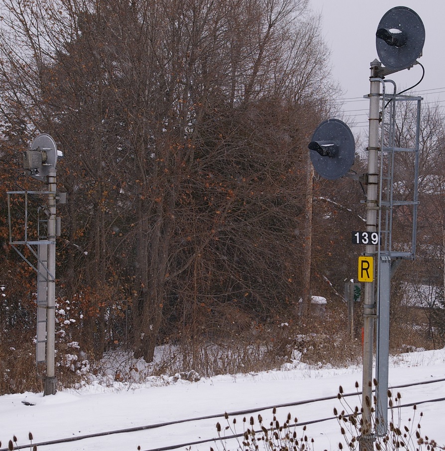
ABS signals mounted back-to-back. Upper staggered head (left) and single head mounted away from track.ABS signals may have a single head, or they may have two heads with a staggered mounting. That is, the two heads do not appear to be directly above and below each other when viewed from a locomotive cab. The head that is closer to the track may vary from one railway to the next. A common practice is to locate the upper head on the same side of the mast as is done with single head signals.
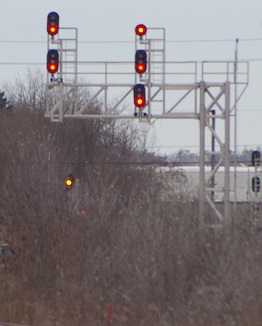
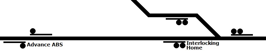
Two-head ABS signals are used as the final ABS signal before reaching an interlocking signal. The reason for this is to provide early warning of a speed restriction at the interlocking, in addition to occupancy information. Sometimes this signal is called an "advance" or "distant" signal to the interlocking, but it is still an ABS signal. It cannot be directly controlled by a Rail Traffic Controller (RTC) or Dispatcher. Like any other ABS signal, its most restrictive indication is either Stop and Proceed or Restricting (if a plate displaying "R" is installed).
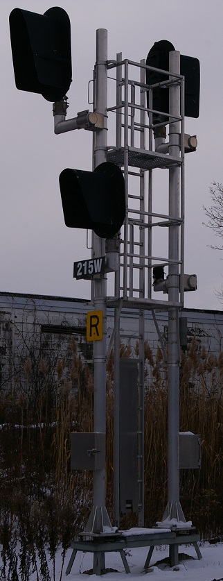
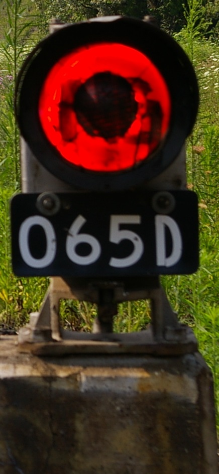
Distant ABS signal only needs single head because interlocking home signal never needs to convey speed restriction since only route at this signal is straight through.When an ABS signal only needs to provide occupancy information, a single head is used. This is the case for all the ABS signals between advance signals, but may also be used for advance signals where there is no upcoming speed indication to convey. This would occur if the home signal protected entry to an interlocking where there would never be a speed restriction.
Where Are Interlocking Signals Placed?
ABS signals are located anywhere except immediately around controlled turnouts because that is where interlocking signals are located. Each entrance to an interlocking will have an interlocking signal protecting entry to the interlocking.
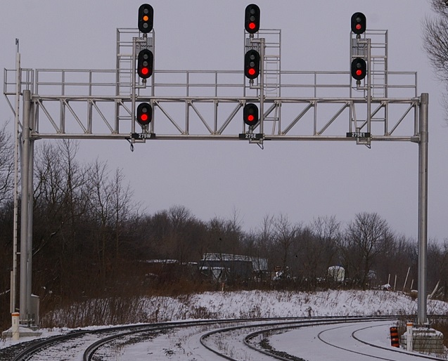
A bridge over three tracks at a CTC interlocking.Unlike ABS signals, interlocking signals are never installed with signals facing opposite directions at the same location. This is because the signal not only protects entry into the interlocking, but it also protects the block beyond the interlocking plant. At the other side of the interlocking, a signal protects entry for trains coming from the other direction for both the interlocking and the block beyond the interlocking. Thus, each directions' signal has some overlap in the track they protect.
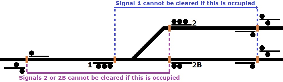
Signal 1 control length includes interlocking and block beyond, which depends on route through the interlocking.
Signals 2 and 2B have a control length that includes the interlocking and the block beyond, if the route through the interlocking is lined for the track the signal controls. Otherwise, the signal cannot be cleared.Interlocking signals will normally display a Stop indication unless a route is reserved by the RTC or Dispatcher. The signal will return to Stop if it is cancelled by the RTC or when a train passes it and occupies the interlocking. In locations where traffic is heavy, the RTC may have the ability to "fleet" an interlocking signal, which means that the route through the interlocking will remain reserved and the signal can automatically change to a permissive indication after a train has passed the interlocking and the block beyond the interlocking.
As there are no signals guarding the exit from the interlocking plant, an interlocking signal not only guards entry to the interlocking, but also to the next block beyond it based on the route that has been reserved. Thus, a signal may only be cleared when a route through the interlocking has been reserved and when the block beyond the interlocking is unoccupied.
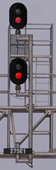
Two-head interlocking signal.
Single-head dwarf interlocking signal.
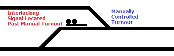
Interlocking signal should be located past manually controlled turnout to allow access to the turnout without needing a route through the interlocking.As the signals around an interlocking plant define its limits, all turnouts within the plant should be controlled as part of the interlocking. If a manually controlled turnout is located near the interlocking, they should be outside the limits defined by the signals. If a manually controlled turnout is within the interlocking limits, a train may only get to the turnout when a route through the interlocking has been reserved and the signal is permissive. This ties up part or all of the interlocking limits for a train movement that does not need most of the interlocking.
Interlocking signals will either have two or three heads. All heads will be vertically aligned, meaning they will be inline above and below each other. For non-main tracks, dwarf signals may be used at interlockings, and these may have one, two, or three heads.
Two-head mast signals are used when not every possible speed restriction is needed. A two-head signal can only convey indications that may be passed at Slow speed (maximum 15 miles per hour), Restricting speed, or at full line speed. If these provide all the speed restrictions needed for the possible routes through the interlocking, a two-head signal will do the job.
If there is a route that can be travelled at Medium speed (maximum 30 miles per hour) or Limited speed (maximum 45 miles per hour), a three-head signal is required.