


During a recent resignalling project, new LED signals were being installed and would be connected to the Signal Animator (SGA) for operation. During installation, it was necessary to check the operation of the signal in case any damage occurred to its wiring, but it was not always possible to have an SGA installed and wired up for testing.
Additionally, even if an SGA was installed, it would be difficult to have an SGA cycle through this in a normal installation. It would also be good to have a test device that can check the operation of the signal that was independent of an SGA in order to confirm any problems were or were not due to the SGA, how it is installed, or the components providing inputs to the SGA.
What was needed was a simple device that had a 4-pin header plug that a signal could be plugged into that matched the pin-out of the outputs of an SGA: Green, Common, Red, Yellow. It would just cycle between each colour, displaying each for a second, and continuously cycling through the sequence.
The project in question had the added complication that some signals use bi-colour LEDs wired common collector, while others used tri-colour LEDs wired common anode. This means the device would need a CA/CC jumper just like the SGA has, and it would need to be configurable for either bi-colour LEDs, where yellow is displayed by powering both the red and green, or tri-colour LEDs, where each colour is a separate output. Though, instead of a soft configuration for bi- and tri-colour LEDs, it would be easier to select using a jumper on a single input.
The device could be battery powered, but the availability of a 5 VDC "wall wart" type power supply made powering it this way easier. Most any PIC microcontroller would work, as the device only needs 2 inputs and 4 outputs, and one output is a power on indicator that could be eliminated. For the project, a PIC16F886 chip was available for experimenting, so this was used.
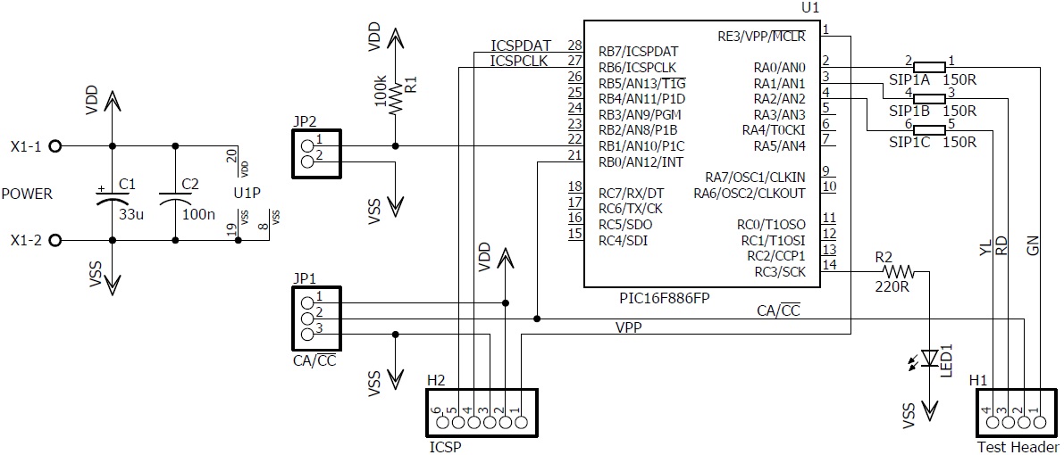
The circuit diagram appears to the right. H1 is the output header, and H2 is provided for In Circuit Serial Programming (ICSP).
JP1 is the jumper that selects Common Anode (CA) or Common Cathode (CC). This connects the common output terminal to either VDD (positive) for Common Anode, or to VSS (negative) for Common Cathode. It also serves as an input to RB0 to let the microcontroller know which is in use. For CC, an output is high for on and low for off, but for CA, the opposite is used.
JP2 is the jumper that selects bi-colour when shorted, or tri-colour when not. It is the input to RB1, and its pull-up resistor R1 is not necessary if the input has an internal weak pull-up available.
SIP1 is a 150 ohm 3-resistor SIP used to limit output current. It is the same component used on the SGA.
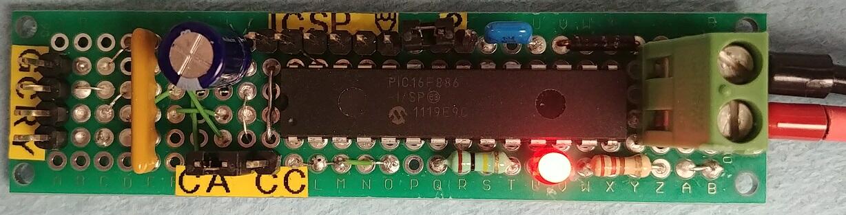
The image to the left shows the Signal Test Jig built on a perf board that is 2 cm by 8 cm (25/32" by 3 1/8").
The connector on the signal plugs into H1 on the left, and the power connects on the right.
The small size makes it convenient when needing to test a signal where its wiring is in a tight space.
Circuits4Tracks does not have any plans to market this as an assembled and tested unit nor as a kit, but we are providing the following for those interested in building their own Test Jig:
- Schematic Diagram, Version 1.00 Last revised: Oct 29, 2020
- Part List, Version 1.00 Last revised: Nov 06, 2020
- Source Code, Version 1.00 Last revised: Nov 06, 2020