


This page provides photos to go with our Traverser Quick Start application note.
Step 1: Power Connection
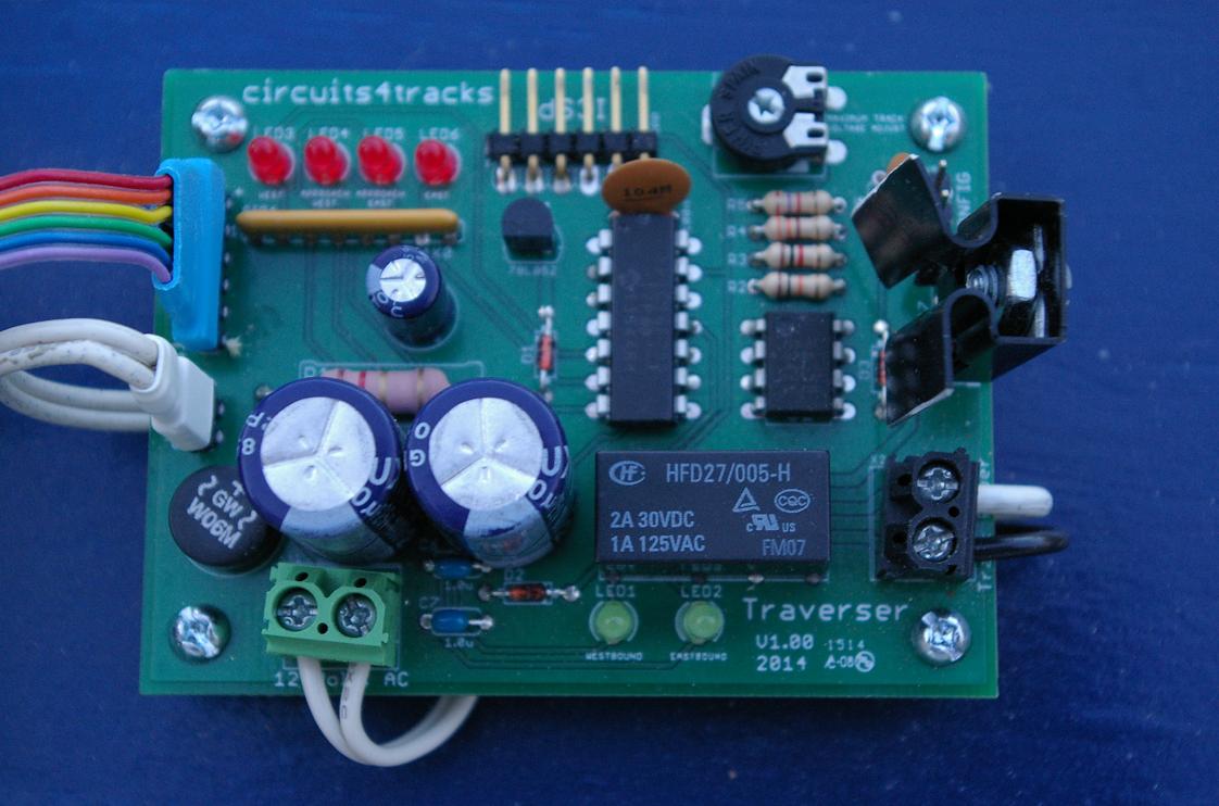
Connect a 12 volt AC power source to the green screw terminal block, labelled X1 in the photo to the right. A pair of white wires connect to X1 at the left side of the bottom edge of The Traverser in the photo.
The power source should be capable of providing enough current to power the train’s operation, but should not exceed 1 ampere.
Step 2: Track Output
Track output is on the black terminal block, labelled X2 on The Traverser in the above right photo. Think of this output just like the output of any cab power pack. In the above photo, there is one black wire and one white wire connected to the track output.
Instead of connecting each of the terminals to one of the rails, only one is directly connected to the common rail. This is the rail with no gaps cut in it. In the examples in the photos, the black wire is connected from X2 on The Traverser to the common rail of the track, seen in the photo to the left.
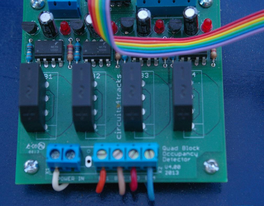
The connection from the other terminal, the white wire in the above-right photo, must pass through the occupancy detector. As can be seen in the photo to the right, the white wire connects to one of the two screw terminals of the X1 terminal block on the Quad Occupancy Detector (QOD).
At this point, do not worry about which terminal connects to the common rail and which connects to the QOD. If train operation is wrong, these can be exchanged.
Step 3: Track Power from QOD to Track
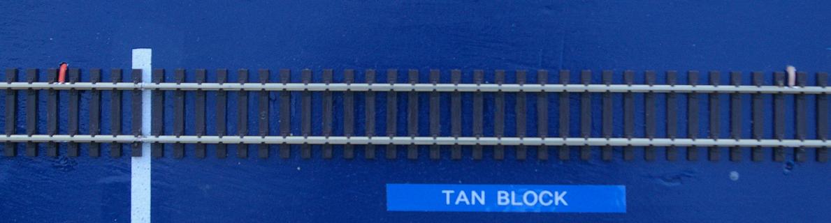
Four track power outputs from the QOD can be found on its terminal block labelled X2 in the photo immediately above to the right. Each one connects to one section of the gapped rail. In the photo, the wires from left to right are orange, tan, red, and blue. They connect to each block of the track's gapped rail in the same order. The left photo below shows the left end of the track, where the orange feed connects to the end block and the tan feed connects to its approach block. The right photo below shows the right end of the track, where the red feed connects to the approach block and the blue feed connects to the end block.

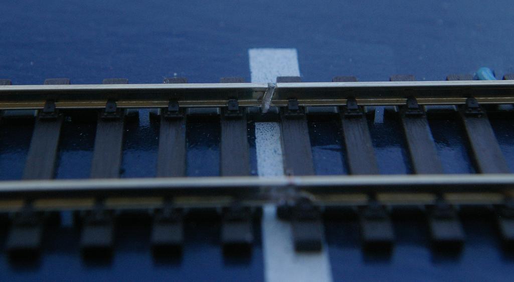
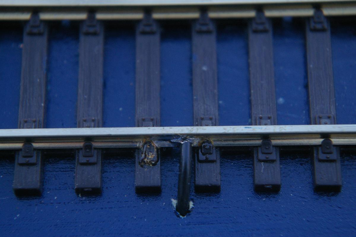
Gaps in the rail separate each block. The photo to the right shows a gap that has been cut and filled with white styrene. The blocks at each end of the track should be long enough for the train to come to a stop.
This length depends on several factors such as the speed of train and its physical momentum. Deceleration begins when the leading power-pickup axle of the locomotive crosses the last gap and takes about a half second. The length needed can be determined experimentally using a regular cab power pack on a test track with the train. Note that if the locomotive is pushing cars that do not draw power, the end block when pushing will need to be long enough for the entire train.
Step 4: Occupancy Feedback to The Traverser
A ribbon cable is used to connect the occupancy outputs of the QOD to the occupancy inputs of The Traverser.
The ribbon cable has an identified side, usually with a red stripe. One end of the ribbon cable should connect to X5 on the QOD, with the identified side at the end ofthe connector labelled V+. This is the end closest to the two-terminal block labelled X3.
The other end of the ribbon cable connects to X3 on The Traverser. Its identified side should be at the end of the connector labelled with a +. This is the end closest to the four red occupancy LEDs.
Step 5: Power-Up Testing
Initial testing should be done by powering up with the locomotive located at one of the end blocks, then repeated with it located at the other end block.
If the initial direction of the locomotive is towards the end-of-track at that end instead of towards the opposite end, switch the track output connections from The Traverser, on the black terminal block, labelled X2. Proper operation should be observed with start-up from both ends.
If you find that the locomotive only heads towards the end-of-track at one end even after switching the track output connections, the problem is likely that you are using a power source that provides direct current, not alternating current. Replace the power source with something that provides 12 volts AC.