A snubber is a device used to suppress effect. In the case of snubber diodes, the effect that must be suppressed is a voltage transient that can either cause electromagnetic interference or, worse, damage controlling electronics.
Voltage transients occur when current is shut off to a coil, such as the coil in a relay. The reason for this is related to how a coil reacts to changes in current. A good mechanical analogy for a coil is a flywheel. When force is applied to the flywheel, its momentum makes it slow to start, but eventually it will reach the intended speed. When the turning force is removed, its momentum tries to keep it turning at the same speed, but it will eventually slow to a stop.
If one thinks of a coil similar to a flywheel, when a voltage is applied to the coil, it tries to resist current from flowing as if it has a high resistance. What is resisting the change in current flow is the impedance of the coil, which is the combination of the coil's actual resistance and it's inductive reactance. When powering a coil with direct current, the inductance only comes into play when the applied voltage changes. This is because the changing current value is creating a changing magnetic field around the coil. This changing magnetic field actually tries to generate an opposing current in the coil, and this resists the current flow. When first applied, like the force applied to a stationary flywheel, the current flow takes a short time to come up to full value just like the flywheel takes time to come up to full speed.
Transient voltages become a problem when it comes time to shut off the relay. Like the flywheel that tries to keep going, when the applied voltage is removed from a coil, current through the coil begins to drop, but this changing current causes a collapsing magnetic field that attempts to generate whatever voltage is needed to keep the current going. This does not last very long, but it can create voltages that are high enough to damage whatever solid state component is controlling the relay.
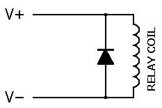
The solution to this is very simple: place a diode in parallel to the relay coil, but make sure it is reverse biased. This means that the anode should be connected to the side of the relay that will connect to the negative voltage source and the cathode on the positive voltage source side. With normal operation of the circuit, the diode does not conduct when the relay is powered. When power is disconnected from the relay, instead of the relay generating a brief high voltage that will damage the driving circuit, the current through the coil that the coil tries to keep moving will follow the path through the diode and the voltage it induces will be limited to the forward voltage of the diode, about 0.7 volts. The maximum current the diode will need to conduct is the current the relay draws when powered, and the peak inverse voltage of the diode must be greater than the supply voltage for the relay.
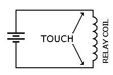
Want to try a simple experiment to see this effect? Take a dry cell or 9 volt battery and apply it to a coil. For best results, the coil may be one winding of a transformer. Connect the battery to the coil as in the diagram to the right. Then touch your fingers across the connections to the coil. You should not feel anything as the battery voltage is low and your fingers are somewhat dry.
While your fingers are still in contact with the wires to the coil, disconnect the battery. As the magnetic field collapses, the coil will attempt to keep the current flowing by inducing a voltage that you should feel for a very brief moment.
Don't keep the battery connected to the coil for too long. The coil offers little resistance to direct current and will drain the battery quickly. Some batteries may begin to heat up if such a heavy load is left connected for too long.
Circuits4Tracks
Affordable Electronic Circuit Design for Model Railroads
 |  |  |  |  |  |