


Disclaimer
This article outlines a project to rewire DCC (Traction) and Accessory (5 VDC) wiring for the author's layout. This article is not intended to be a standard for how anyone should wire their layout, but rather a guideline of tips to help make wiring that hopefully has few, if any problems, but should problems occur, be easier to discover and repair faults.
Aside from the use of Circuits4Tracks products, the author has no vested interest in the other products and materials used, or their suppliers. No remuneration and no purchase discounts were received for items mentioned in the article and listed with suppliers at the end.
Layout Background
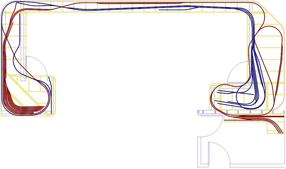
Figure 1The N scale layout is located in a finished basement room that is about 33' by 20'. Shown in Figure 1, there are two L-shaped sections on opposite walls of the room connected by a 16" deep shelf between the two. On the right (south) side of the room, there is a separate workroom that has a staging yard off of a main track that passes through the wall to enter and leave the room.
The layout is loosely based on the Canadian National (CN, shown in blue) and Canadian Pacific (CP, shown in red) mainlines in and to the east of Toronto. Station names on the two lines are taken from real station names, positioned relative to each other, but with a degree of freelance licence. The two main lines are both designed to be point-to-point for operation, but there is a connecting track between the two at each end to allow for continuous running for the benefit of non-model railroaders wishing to see the layout. Instead of the CP mainline ending at the staging yard, it continues and loops back on itself, providing a small loop for continuous running in the early days of the layout.
The basement was finished by the spring of 2008 and layout construction started later that year (and continues to this day!). The benchwork is steel studs installed as part of finishing the basement. Each side of the room is supported by a 52" tall half wall of steel 2x4 studs sitting on a wood 2x4 base plate screwed into the concrete floor with sill seal used for protection from the concrete. This keeps the steel from contacting the floor and provides something for baseboard to be nailed to. Each side section has its own access door. All corners of the room where the layout exists are curved from the layout up to the ceiling to make them more or less invisible. Above the front edge of the entire layout is a valance that hides track lighting that can be controlled to provide night and day for the layout. The walls and ceiling out to the valance are painted as sky. Yes, the plan is to not move from this home.
The base support of the layout is made of 2x3 steel studs on top of the 52" half walls. The "shelf" section along the east wall is supported by 2x3 steel studs that angle into the wall where they are supported about 18" below the layout. The top 4" of this angled part originally had wood access hatches attached by piano hinges, but this was widened to 8" during rewiring.
Original Wiring
From the start, DCC would be used for train operation (traction power). The DCC power would make use of two 5 Amp power boosters, one for the south half of the room and the other for the north half.
For each half of the room, there would be four separate DCC power buses to prevent a short circuit on one from affecting the others. The CN and CP main lines would each have their own bus. A third bus would be for any yard and spur tracks - non-mainline track that would not use block detection. The fourth bus would be for accessory decoders for switch machine operation. As the first three buses could experience a short circuit from derailed wheels, these were protected by electronic circuit breakers.
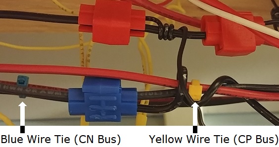
Figure 2Bus wiring used 14 gauge solid wire, red insulation for the non-common side and black insulation for the common (ungapped) rail side. These would be twisted together, about 3-4 twists per foot. As there were four buses using red and black wiring, coloured wire ties were placed on each bus every few feet to help with identification, as shown in Figure 2.
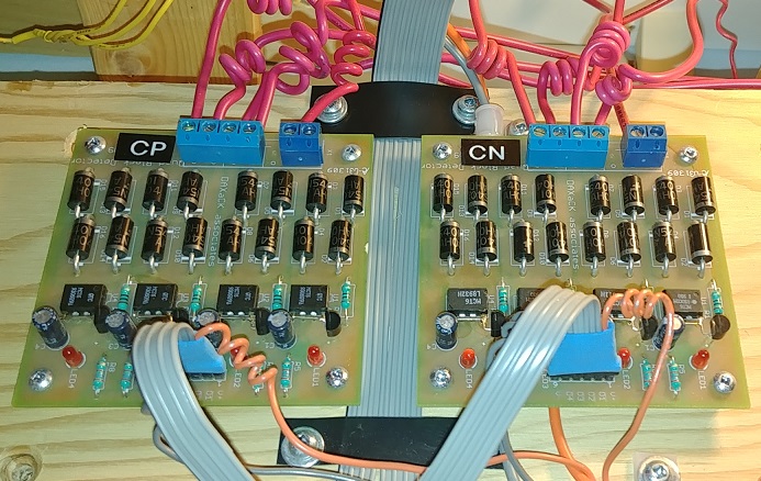
Figure 3For the mainline buses, the red wire would feed the occupancy detectors that would then feed the gapped rail of track blocks, as seen in Figure 3. Insulation displacement ("suitcase") connectors were used to take 18 gauge solid wiring off the bus to occupancy detectors, as seen in the image of Figure 2. Track feeders used 22 gauge wire with a maximum length of 18". In most cases, 18 gauge wire was used from the occupancy detector to the track feeders.
After the DCC wiring was well underway, it was determined that power for other purposes, including signalling, building lighting, street lighting, and anything else would be kept simple by using only 5 VDC. Electronics such as occupancy detectors and signal drivers (the forerunner to the Signal Animator) use 5 volt supplies and since all other lighting would make use of LEDs for low power consumption, there was no need for any other supply voltages. Using red and black for a DC power bus would seem natural, but could be confused with the DCC buses. The closest available insulation colours were orange and grey. Though these were not easily available in 14 gauge, the power level was lower than the DCC requirements and 18 gauge was used for the bus.
Thinking About Change
This wiring worked well for over a decade, and would likely continue to work well. Problems were few, but during the construction of one yard, a problem came up that required the need to provide a way to isolate parts of the yard bus in order to find the fault. This was accomplished with the use of inline connectors, but these were only added where needed to solve the trouble.
The use of orange and grey wire for the 5 VDC bus always bugged me, though that is a personal thing which may not be an issue for others. The use of all solid wire has not been an issue, but occasionally its stiffness gives it a bit of a mind of its own. It is said that stranded wire is better for the frequencies used with DCC, though I cannot say if this actually makes a difference for the typical home layout.
The real urge to rewire the layout came for me several years ago when I started working as a maintenance trainer for a rail signalling company. I work with customer trainers and sometimes with their signal maintainers to perform fault finding on the signalling equipment. Working with the prototype equipment and seeing how a new installation is done and documented, made me begin to feel that my layout was not exactly well wired. Sure, I did things reasonably neatly, and each occupancy detector card was labelled, but I never documented the wiring and in trying to trace through it to create a sketch of each bus, it became clear it was not so neatly done.
Goals for the Change
I came up with the following specifications:
- Use stranded wire everywhere, except for track feeders
- Use red and black for the 5 VDC power wiring
- Use suitable, easily obtainable colours for DCC wiring
- Document the wiring - plan out the wiring ahead of time, and update the documentation to match the as-built installation
- Label all wiring
- Use DIN rail terminal blocks, with the ability to isolate (disconnect) parts of the wiring for ease in fault finding
- Keep things as neat as possible
The idea would be to have terminal block assemblies (TBAs) at key points around the layout, that I call �regions'. Regions are basically where one or more occupancy detector cards, accessory decoders, or a DCC power booster are located.
Terminal blocks with an isolation link are used to isolate whatever is downstream from that TBA. That is either the next TBA or the DCC power feed to an occupancy detector or accessory decoder, or 5 VDC power. Isolation is only be on the non-common side of DCC power, or on the positive side of 5 VDC power.
Main bus runs, from one terminal block to the next, only use 14 gauge wire. The easiest source of 14 gauge stranded wire is from the electrical department of the local home centre. The colours of this type of wire are limited to black, white, red, blue, and green. Green is used for grounding (earthing), so only four colours remain. Since the 5 VDC bus will use red and black, that leaves blue and white for the DCC wiring. Since white is used for the neutral in Canada and the USA for electrical wiring, I decided to use it for the DCC common conductor, leaving blue for the non-common side. The same colours were used for terminal blocks for consistency, with the exception of the terminal blocks with isolation links, as these are only available in beige from Dinkle, the manufacturer of terminal blocks I am using.
18 gauge stranded wire for other feeds is easily obtained in these colours from an electronics supplier I use. The 22 gauge red and black track feeders already installed would not be replaced, as these are soldered to the rails and many are in locations where the track has been ballasted. The solution was be to use white and blue heat shrink tubing on the feeders. Any 22 gauge orange and grey wire that would not be replaced could get red and black heat shrink tubing as well.
Figure 45 VDC Power
The existing signalling system uses a dedicated I/O controller that is powered with a standard ATX computer power supply. This provides at least 10 Amps on its +5 VDC outputs. This provided the power for the 5 VDC bus on the south side of the room as well as the "shelf" part of the layout. A small "wall wart" power supply provided 5 VDC at up to 2 Amps for the north side of the layout.
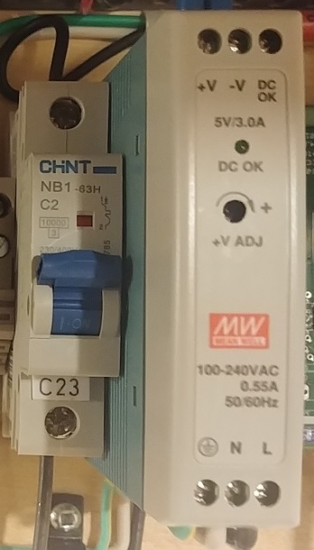
The I/O controller for the signalling system will be replaced in the future, so a new source of 5 VDC power was needed. An economical choice was to go with DIN rail mounted switching power supplies by Mean Well, as seen in Figure 4. These power supplies are relatively inexpensive, costing about CAD$20 each, and each can provide up to 3 Amps of current. Being switching power supplies, they can accept an input voltage from 100 to 240 VAC. A DIN rail circuit breaker is used as a disconnect for the power supply to make it easy to shut off when performing work on the wiring.
For 5 VDC power with the new wiring, the layout was divided into three sections with one of these providing the bus power for each. If the current draw in a section get too close to the 3 Amp limit, the new terminal block wiring will make it somewhat easy to modify and split a 5 VDC bus if needed and add another power supply.
Another feature of these power supplies is that they have a "power good" output. Each supply will feed an input to the signalling computer system so that an alarm will be generated if there is a problem.
DIN Rail Terminal Blocks
Figure 5Many may see this type of terminal block as a bit of a luxury item, but their ability to help keep wiring neat and, with the use of units with disconnect links, can greatly assist in keeping the wiring neat and simplifying fault finding tasks.
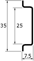
DIN Rails are steel or aluminum rails of standard sizes that terminal blocks and other devices are installed by clipping them on. The rails may be mounted in equipment racks or on flat surfaces. There are a few different rail profiles, and many terminal blocks are designed to fit multiple profiles, but the most common is known as top hat rail as shown in Figure 5, such as power supplies and circuit breakers, are likely to only be mountable on this type of rail. Rail can be purchased in longer lengths that are easy to cut with a hacksaw, or in pre-cut lengths of various sizes.
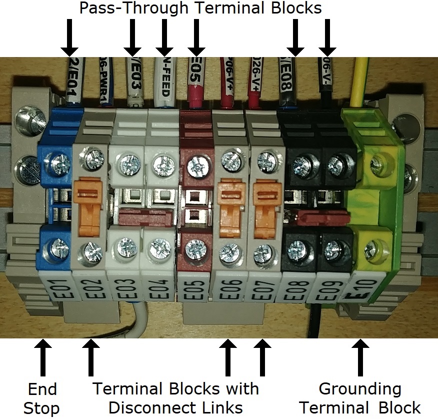
Figure 6Terminal blocks come in many different configurations. To keep things simple, this project used only three types. Shown in Figure 6, the first type used is the basic pass-through terminal block from Dinkle, known as te DK4N series. Each terminal block is 6.1 mm wide (about ¼") and is available in numerous colours that are specified with a suffix on the model number (DK4N-BL, DK4N-WE, DK4N-RD, and DK4N-BK).
Depending on the quantities purchased, these can range in price from about $0.35 to $0.50 (USD) each.
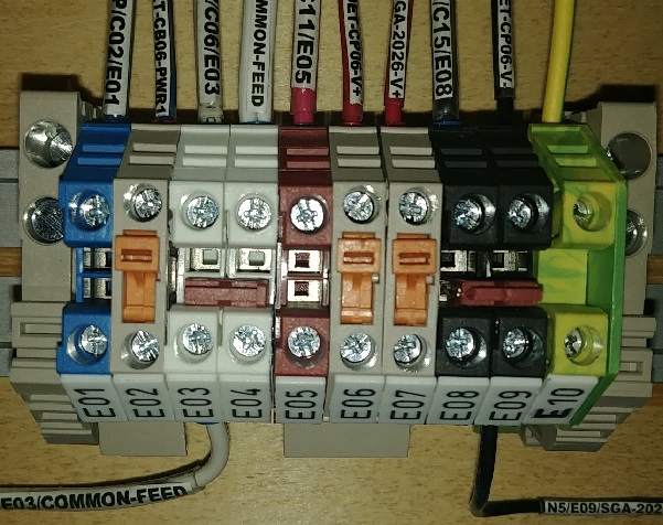
The pass-through terminal blocks have an electrical connection between its top terminal and its bottom terminal. These blocks have openings in the middle that an insertion bridge can be installed to electrically connect adjacent terminal blocks. The two white (E03 and E04) and the two black (E08 and E09) blocks are connected with insertion bridges.
The bridges come in sizes for connecting 2 to 10 blocks, but I simply ordered the 10 (DSS4N-10P) and cut them as needed.
An alternative way to connect adjacent terminal blocks is with the use of an insertion bridge that installs in the screw terminal. I also purchased only the 10 position bridges and cut them as needed (CSC-410PN). On the TBA shown in Figure 6, the blue wire of a DCC bus is brought in on the top of E01 and a bridge at the bottom connects it to block E02 that has a disconnect link. The blocks with disconnect link, part number DK4N-T, are only available in beige.
The top of E02 feeds power to a block detector. The positive side of the 5VDC power comes in at the top of E05 and is distributed to E06 and E07 by a bridge at the bottom. As described earlier, disconnects are not used for the common side of the DCC bus (white terminal blocks) and the negative side of the 5 VDC power (black terminal blocks).
Each DIN rail is bonded to ground with the use of a grounding terminal block (E10 in the image, part number DK4N-PE), which has a wire that is connected to the steel framing of the benchwork. The grounding terminal block is electrically connected to the DIN rail it is mounted on. Where a TBA is located at a DCC power booster, the grounding terminal block also has a connection to the grounding conductor of the power source. Green wire could have been used for grounding, but I have yellow/green earthing wire from the UK and I like its higher visibility. Additionally, it also matches the yellow/green colour of the grounding terminal blocks.
Each 5 VDC bus has its negative side bonded to ground at the TBA where it is located. DCC power boosters are bonded to ground, but neither terminal of their outputs can be bonded to ground.
There are two other components visible in the image. The easiest to spot are the end brackets, part number SS2. These attach like the terminal blocks, but have a one or two set screws to lock it in place on the rail. The SS2 has two set screws and can be used with different rail profiles. For top hat rail, the top screw digs into the rail while the other pinches it. The less visible component is the end cover, part number DK4NC with a suffix for the colour. Only one end cap is needed as terminal blocks are open on only one side. The colour of the end cap matches the terminal block it is next to, which makes it more difficult to spot. In Figure 6, it is the same yellow/green colour as the grounding terminal block.
Bus Naming
Following on the original wiring, the same DCC buses would be used: CN Main, CP Main, Accessories, and Yard/Spur. Each side of the room would have separate instances of these buses supplied by a separate 5 Amp power booster. The track buses would each make use of an electronic circuit breaker for over current protection with automatic restoration, while the accessory buses would make use of a 2 Amp DIN rail circuit breaker. As already described, the 5 VDC power made use of three separate buses. Even though each part of the room had separately powered buses, the same name would be used for each section's bus of the same purpose.
In prototype railway signal wiring, power buses are designated by their voltage and each side of the supply use the letters "B" and "N" for direct current buses, or "BX" and "NX" for alternating current busses. For example, a 24 VDC bus would have its positive side named "B24" and its negative "N24". Following this, the 5 VDC bus wiring uses the names "B5" for the positive (red wiring) side and "N5" for the negative (black wiring) side. To make these easy to remember, think "bus" for the B side, and "negative" for the N side.
As DCC power is really an alternating current, using "BX" and "NX" would be the likely choice, but as the names would be longer than a number, I just used "B" for the non-common (blue wiring) side and "N" for the common (white wiring) side. For alternating current, the word "negative" does not apply, so think "neutral" for the N side.
The names of my DCC buses are:
- CP Main: B-CP and N-CP
- CN Main: B-CN and N-CN
- Yard/Spur: B-YRD and N-YRD
- Accessories: B-ACC and N-ACC
These names are not only be used on wiring diagrams, but are an important part of the labelling for the wiring.
Wire Labels
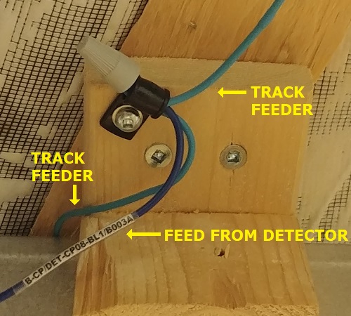
Figure 7Part of keeping the wiring neat and organized was the need to have every wire labelled at each end, with the exception of the track feeders themselves. Track feeders are kept short and connect to wiring that is labelled with a wire nut and secured in place, as show in Figure 7.
The labels need to be as short as possible, but have to provide three pieces of information:
- What the wire is used for (the bus name)
- Where the source of power comes from (the upstream end of the wire)
- The destination of the wire (the downstream end of the wire)
Figure 8On the label, each of these are separated by a slash (/) character. The first is simply the name as described above. The second and third are the terminal name that the wire is connected to. If it is a terminal block, then the label of the terminal block is used, such as A05 or E08. Most wiring connects to the top side of terminal blocks, but there are a few exceptions where the bottom is used. Wiring diagrams clearly indicate top and bottom for terminal blocks, but for the wire labels, I chose not to distinguish it since it is not common to use the bottom.
Terminals of a device will be named using the device and how it labels its own terminals. For occupancy detectors, I have named each with "DET-", its railway initials, and its two-digit number. This name appears on labels followed by a dash and the terminal used ("PWR1" for bus input, "PWR2" for bus downstream feed when used, or "BL1", "BL2", "BL3", or "BL4" for the track feeds). In the photo above, the label shows "B-CP/DET-CP08-BL1/B002A". "B-CP" is the bus name, "DET-CP08-BL1" is the power feed output on the occupancy detector, and "B002A" is the block name being fed.
For accessory decoders, they are named with "ACD-" followed by the decoder's number. For Signal Animators, each labelled with the signal number it operates, so the name will be something such as "SGA-1982". Each will then have a dash and the terminal name.
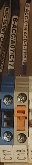
In Figure 8, the label on terminal block C17 is "B-ACC/A07/C17" and indicates this is feeding "B-ACC" power (accessory bus non-common) coming from terminal block A07.
Figure 9Terminal block C18, feeds "B-ACC" power to "ACD-1-TRK1", which is the terminal named "TRK1" on accessory decoder 1. Note that terminal block C18 has an isolation link. To disconnect bus power to accessory decoder ACD-1, the orange link can be pried open with a small slotted screwdriver.
Labels are simply laser printed on paper and slipped into a piece of clear heat shrink tubing at the end of the wire and heated to lock it in place.
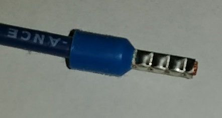
Since stranded wiring is used, it is possible for a stray strand or two to not go where it is intended during installation. To prevent this, all wires have ferules crimped on their ends, as shown in Figure9. The ferule must be installed after the label.
Figure 10Mounting Devices on DIN Rails
Various hardware is available for mounting circuit boards on DIN rails. Dinkle has a line of circuit board carriers in a few different sizes. Their KMRC line is made for boards that are 72 mm wide. The Circuits4Tracks QOD is just under this size, but fits well in this carrier by using a small strip of styrene H column. The I/O cards for our new signalling system are being designed to fit this size, so these carriers are ideal for mounting detectors and I/O cards.
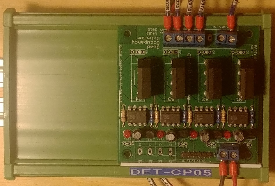
The carrier comes in various lengths, but the most flexible choice is the 1 metre length that you can cut to the desired lengths. Once cut, each end piece (KMRML and KMRMR) simply slide on the ends and are held with a pair of screws. The end pieces snap onto the DIN rail. Figure 10 shows a QOD mounted on a carrier.
Figure 11Slotted Wiring Ducts
To keep things neat, wire ducts are used to contain wires running from TBA to TBA as well as from a TBA to other devices, as shown in Figure 11. The ducts have slots on each side where wires may enter or leave the duct.
Since every wire is labelled on each end, there is no need to trace a wire through the duct to figure where it goes. The duct keeps wiring neatly out of the way, and the only visible wiring are the last portion to track feeders.
Figure 12Documentation
Creating the plan for the wiring was an important part of determining the terminal block requirements. Each region has its own drawing, called bookwiring, showing the connections to other regions as well as to devices in the region. The labelling on the bookwiring sheet provide the information needed to print wire labels.
Some portions of the drawings needed to be completed when the wiring was being updated. For example, signals were being upgraded and Signal Animators were being installed to replace older circuits. The wiring of the 5 VDC supply for SGAs was developed as the rewiring progressed. This was due to determining the optimal location for each SGA.
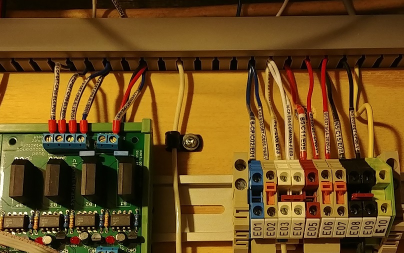
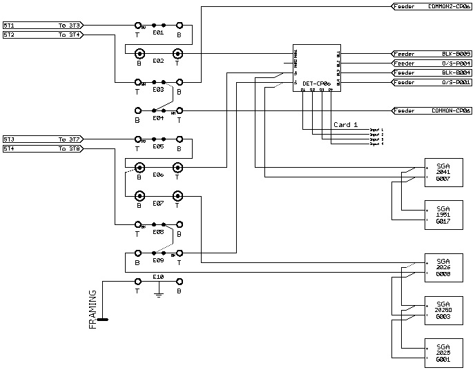
While the topic of creating bookwiring is beyond the scope of this article, and is planned as the subject for a future article, we will take a look at the bookwiring for TBA-E as it is a fairly simple region that only has the CP DCC bus and 5 VDC power. This terminal block assembly is shown in Figure 12, with its bookwiring shown in Figure 13.
Figure 13The bookwiring diagram for this terminal block has been compressed a little for this article. The actual sheets have things spaced out a little more. Also, wire labels have been removed as they would be somewhat difficult to see here.
Figure 14
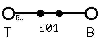
Figure 15The symbol for a pass-through terminal block is shown in Figure 14. The two letter code indicates its colour: "BU" for blue, "WH" for white, "RD" for red, or "BK" for black. Connections to either of the two dots in the middle are for insertion bridges. Each terminal is labelled to indicate its position, usually "T" for top and "B" for bottom where the TBA is mounted horizontal. For vertical mounting, "L" is used for left and "R" is used for right. There are two situations on the layout where a TBA is mounted on the bottom of the layout, when looking at it from below, "F" for front and "B" for back are used.
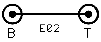
The symbol for terminal blocks with isolation links are shown in Figure 15.
Project Completion
At the time of writing this article, the rewiring project is about 98% complete. The final portion is in with the newest part of the layout, where some of the wiring is new and not replacing existing wiring. The existing wiring is now significantly neater that what it replaced and the use of terminal blocks has already shown its value for checking power and being able to electrically isolate portions of the layout when other work is being performed.
This rewiring was being done in conjunction with installing the new Switch Machine Interface (SMI) product by Circuits4Tracks to improve the wiring and documentation of switch machine control and monitoring. It was also being done along with the replacement and new installations of new wayside signals and their Signal Animators (SGA). The next project will be the replacement of the existing signalling controller with the new Circuits4Tracks system currently under development.
Materials Used and Suppliers
DIN Rail Power Supply
Amazon has a number of DIN Rail power supply units. The unit used for 5 VDC power was model MDR-20-5 from Mean Well. It is rated for an input of 100 to 240 VAC at 50 or 60 Hz, and an output of 5 VDC at up to 3 A.
Ferules
Amazon has numerous kits containing variouss ferule sizes and a crimping tool for a reasonable price. Purchasing additional ferules is also relatively inexpensive on Amazon.
Terminal Blocks, DIN Rails, and Circuit Board Carriers
Dinkle is the manufacturer of the terminal blocks and circuit board carriers used. The supplier used is International Connector, and can be found at their Amazon Store. They sell terminal block kits containing a variety of components for a particular assembly and they can provide the specific quantities needed for the project at hand.
Here are the individual parts used in this project:
- Pass-through terminal blocks: DK4N-BK, DK4N-BL, DK4N-RD, DK4N-WE
- Isolation link terminal blocks: DK4N-T
- Grounding/earthing terminal blocks: DK4N-PE
- End covers: DK4NC
- End brackets: SS2
- Insertion bridges (top): DSS4N-10P
- Insertion bridges (screw terminals): CSC-410PN
14 Gauge Stranded Wire
This wire was purchased at The Home Depot, as it is sold by the metre and could be obtained as needed. Some other hardware, such as screws, wire straps, and brackets for mounting wire ducts were also purchased here.
18 Gauge Stranded Wire and Slotted Wire Ducts
These items can be purchased from a number of electronics suppliers. In the Toronto area, Sayal was used. They do ship within North America.