


This article is the culmination of a question posted on Usenet
|
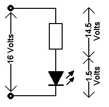
One great benefit of LEDs is that they use a small fraction of the power of incandescent bulbs. Some incandescent bulbs can required 50 to 100 mA (milliamps) of current to operate, while LEDs can be found that provide the same amount of light with as little as 10 mA. This greatly reduces the load on the power supply used, but note that your mileage may vary! Before getting into the numbers for LEDs, let us start with some electrical basics. It is common to use the analogy of water in pipes when describing an electrical circuit, as this works well for direct current (DC) circuits or alternating current (AC) circuits with resistive loads. There are four basic measurements you may need to deal with when designing a circuit: voltage, current, resistance, and power. Think of voltage like the water pressure, current is like the amount of water flowing, and resistance is related to the size of the pipe - the smaller the diameter of the pipe, the more resistance to the flow of water. For a given pressure, if you wanted to double the amount flowing, you can double the pressure or cut the resistance in half by doubling the cross-sectional area of the pipe. This means that current is directly proportional to the voltage, but inversely proportional to the resistance. This is where the Ohm's Law equation comes from: I = E ÷ R Where I is the current in Amperes (or Amps, for short), E is the voltage in Volts, and R is the resistance in ohms. This equation can be re-arranged to find any one of the three values when you have the other two: E = I × R R = E ÷ I The second arrangement will be useful for working with LEDs. Power is the amount of work you get, and it is the product of the voltage and the current. Thinking of the water, if you wanted the water to spin a turbine, the amount of power available to spin it is the product of the pressure and the flow. Increasing either of these will increase the power you get. However, given that the rest of the circuit (or pipes, in the case of water) may have a fixed resistance, if you increase the pressure, the fixed resistance will mean that you will also increase the flow by the same amount. If you doubled the pressure with the same resistance, then the current will also double. This results in a quadrupling of the power! The power equation is: P = E × I Where P is the power in watts. If the resistance in the circuit is fixed, then I can be replaced with "E ÷ R" from Ohm's Law and the power equation becomes: P = E² ÷ R This is why the power is proportional to the square of the voltage. Power calculations will be important when choosing resistors. When current flows through a resistor, a voltage drop will exist across it. Since voltage multiplied by current is power, this means that the resistor will have to dissipate some power, and it will do this in the form of heat. Resistors have a power rating, which tells you the maximum amount of heat they are physically able to dissipate with a normal amount of space around them. If you stay within that limit, the resistor will last a very long time. If you are using your DCC system for power, be aware that the bus actually has an AC voltage that is about 16 volts. LEDs only conduct electricity in one direction, so you either have to rectify the bus power to get DC, or power it directly where it will only draw current half the time. You won't see it flash on and off because of this, since the frequency is too high for you to notice. What you will notice is that the LED will not be as bright powered this way compared to pure DC, but you can compensate for this if you don't like the brightness. It does mean that you could power a second LED wired in the opposite direction to take advantage of the capacity of the power supply that you are not using half of the time with the first LED. The current rating of the system is the maximum current it is capable of supplying. Think about the maximum flow of water - if you have a 'water saving' faucet that only allows 2.5 gallons per minute to flow, that's all you will get, regardless of how much you open the tap. You might get less if the tap is open just a bit, but 2.5 is the maximum. With a DCC system that has a 5 Amp capacity, not only is it capable of no more than 5 Amps, but it also has circuit breaker protection that limits the output to 5 Amps. That way, if a short occurs and current flow exceeds the limit, it shuts off the output. Unlike a circuit breaker in your home, you don't have to reset it manually. The system will 'test' its output every couple of seconds, and if it sees that the load trying to draw more than its limit is not there, it restores the power. Every device you connect to that DCC system will draw current. If you have an LED to light a building that draws 20 mA (see below for how you do that), then your 5 A power supply has the capability of powering 250 of these before you reach its limit. Of course, the big power draw will come from your locomotives when they are actually moving. N scale locomotives can draw around a quarter to a third of an amp, and HO scale locomotives draw in the range of a third to a half an amp. If not actually moving and with all lighting off, a locomotive's decoder will only draw a few milliamps. It is a good idea to have an idea of how much current is being drawn by your layout when you want to add something new that will draw more power. Now, on to LEDs. An LED is not a passive device like a resistor, so it is not possible to simply put a voltage across it and measure the current through it to find out a resistance value. An LED has something called a "forward voltage", which means that it will not conduct at all (except for an extremely tiny �leakage' current) until it reaches that voltage. Once you reach that forward voltage, the tiniest increase in voltage will cause a huge jump in current flow. If you exceed the LED's maximum forward current rating, it will be destroyed. It is necessary to use a resistor in series with the LED that has a value that will limit current in the circuit, at the voltage of your power supply, to a value that is less than the LED's maximum current. In most cases, you will actually limit the current to somewhat less than it's maximum. For instance, an LED might be rated to provide a certain amount of light (in units of millicandela, or MCD) at a current of perhaps 20 mA. That same LED may have a maximum forward current limit of 60 mA, so you would likely design a circuit for only 20 mA or even less. From the point where an LED starts to conduct current all the way up to its maximum current rating, there is only a small change in the voltage across it, so for the purpose of designing a circuit, it is safe to assume that it is constant. This voltage drop will vary from one type of LED to the next, but it is generally between 1 and 2 volts, though there are some even higher. I like to use 1.5 volts as a rule of thumb as a starting point. This will easily allow the calculations for figuring out the resistor needed to limit its current. For another rule of thumb, most LEDs tend to have maximum currents above 30 mA, but many recent LEDs, especially white ones, will provide all the light you need with as little as only 10 mA.From the point where an LED starts to conduct current all the way up to its maximum current rating, there is only a small change in the voltage across it, so for the purpose of designing a circuit, it is safe to assume that it is constant. This voltage drop will vary from one type of LED to the next, but it is generally between 1 and 2 volts, though there are some even higher. I like to use 1.5 volts as a rule of thumb as a starting point. This will easily allow the calculations for figuring out the resistor needed to limit its current. For another rule of thumb, most LEDs tend to have maximum currents above 30 mA, but many recent LEDs, especially white ones, will provide all the light you need with as little as only 10 mA.From the point where an LED starts to conduct current all the way up to its maximum current rating, there is only a small change in the voltage across it, so for the purpose of designing a circuit, it is safe to assume that it is constant. This voltage drop will vary from one type of LED to the next, but it is generally between 1 and 2 volts, though there are some even higher. I like to use 1.5 volts as a rule of thumb as a starting point. This will easily allow the calculations for figuring out the resistor needed to limit its current. For another rule of thumb, most LEDs tend to have maximum currents above 30 mA, but many recent LEDs, especially white ones, will provide all the light you need with as little as only 10 mA. |
|
|
I will usually start with the assumption that the forward current should be 10 mA and the voltage drop is 1.5 V. Here is how you go about figuring out the resistance you need:
|
STANDARD RESISTOR VALUES If you have 10% tolerance resistors (silver is the last stripe), the values available are multiples of: 1.0 1.2 1.5 1.8 2.2 2.7 3.3 3.9 4.7 5.6 6.8 8.2 If you have 5% tolerance resistors (gold is the last stripe), the values available include the above, plus values roughly half way in between: 1.0 1.1 1.2 1.3 1.5 1.6 1.8 2.0 2.2 2.4 2.7 3.0 3.3 3.6 3.9 4.3 4.7 5.1 5.6 6.2 6.8 7.5 8.2 9.1 |
|
If you find the LED is too bright, try using a higher resistance value. If it is too dim, a lower value resistor may be used provided the current does not exceed the LED's maximum current rating, and I would recommend staying below 90% of the maximum rating. If you do not know the maximum current rating for the LED, I would keep the current below 30 mA. If it is still too dim, try a different LED with a higher brightness. Be aware that there may be an issue with something called the maximum reverse voltage when powering an LED from an AC source. The reverse voltage limit is the maximum voltage that can be applied to the LED in reverse before it breaks down. Sometimes, this can be as low as a few volts, so for protection from reverse voltage, you can add a rectifier diode in series with the LED/resistor. Something like the 1N400x family of diodes works fine. Now, this diode will have a voltage drop of about 0.7 volts, so in your calculations above, this will have to be included. |
|
|
That means subtracting 2.2 volts from your supply voltage. In any case, if you do the calculation without the diode and later add it, it will lower the current through the LED, so no harm is done - it will be slightly dimmer when lit. |
|